
05/22/2013
05/22/2013
Pyro 37 Chevy Build

For the new series that Harry was suggesting I decided to give it
a shot. Starting with an original kit I started hacking the fenders so I could
get an idea of my wheelbase.

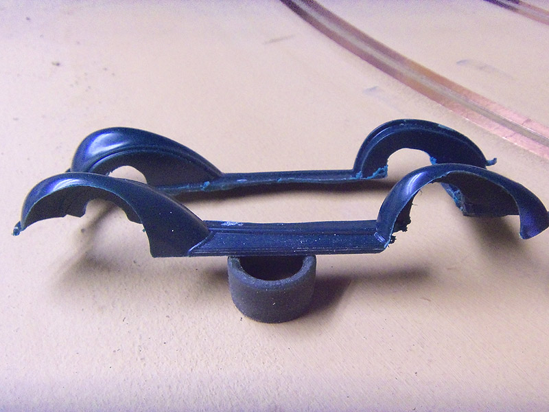
In this photo you can see the hogged out fenders and also the relief in the inner fenders for the axles. Yes, I do things a bit backward sometimes but it works for me. Also sometimes my solder work isn't the prettiest as will be seen in the photos.
For the chassis I used 3/32 square brass tube.

I cut my cross members to fit just inside the fender unit.

Another note, if using plastic wheels for your setup and
soldering, make sure they are a spare set. The heat from all the soldering does
transfer into the axles and into the wheels, most times ruining the hubs. The
axles are 3/32 and the tubes they set in are 1/8". I used 1/8" risers to pick
the frame up of the track. The next one I build will use 3/32 risers so as to
hide more of the chassis inside the fender unit.

Here you can see the basic chassis under the car. When the rear axle tube is
soldered in place cut the tube inside the frame rails in the rear. Now you have
your carrier with automatic bushings.
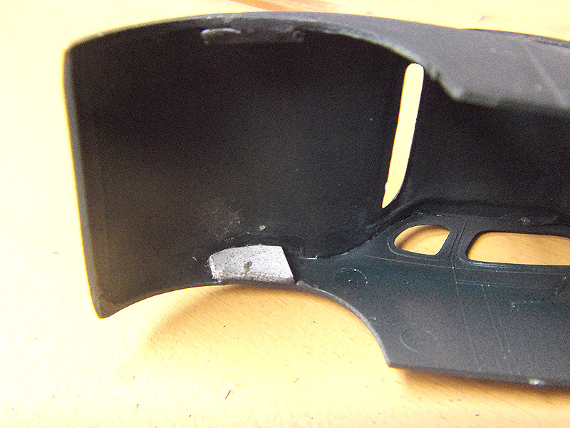
Moving on to the body, If your using an original kit I can't stress enough to
put some backing material on the body seams. If you use filler to smooth out
your body the glue joints get stressed and your filler cracks as you sand things
out.
Once it's roughed out I do a mock up to see just where I stand.

Looking pretty good so far.

Now we have it this far lets move to the guide flag assembly.
For this build I'm going to use a Scalextric guide flag. To do this you will need some flat strip stock and some 3/16" round brass tubing. Fashion an "L" bracket. Then drill a 3/16" hole for your tube.

Here you can see I have already soldered and cut my tubing. To do
this I solder a piece of round tubing a bit longer than what I need then trim to
fit my guide. The large hole is for routing my wires. Once the tubing is in
place you will need a small rat tail file to open the inside of the tube just a
touch to free everything up.
Next I use a spare guide with braid to set my height. Again, using a spare part for set up keeps from melting my good parts. My front wheels are setting on some card stock. This gives me a decent tripod effect strait on.
Next I assemble the rear end to make sure I have enough clearance
for the gear. Here I had to cut a bit more of the fender unit so everything
would clear. This particular gear is a Slot It.

Next I take all the bits and pieces off all the way to a bear
frame. Then I solder a piece of flat brass to the bottom of the chassis. One
reason for this is to add some weight to the bottom of the car and also I plan
on using Velcro to mount the body.


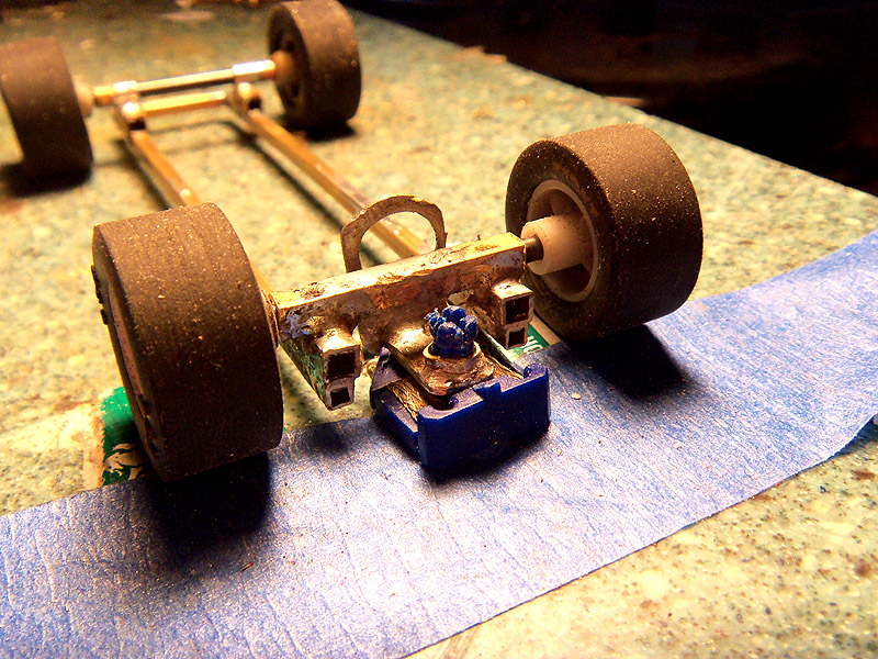
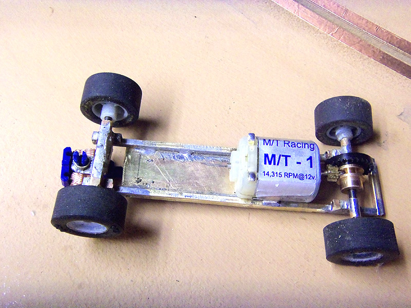
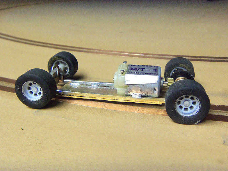
Now I set the motor in and solder in place. As can be seen in the photo it is a
MT-1. These motors come from Mark Thomas and MT Racing. I can't say enough good
about this motor. They have the right scale speed for classics. They are smooth
as glass and have enough power to drift in the turns.
Let's move on to the body mount. I planned to use Velcro to mount the body. My problem was with the brass plate on the bottom of the chassis my Velcro was flush with the top of the rails. To fix this I decided to solder a small piece of brass to the bottom plate. You could super glue a piece of plastic to the plate, but using the brass gives us a little more weight to the chassis.


At this point I would usually bring it back to a bare frame to get it ready to paint. A quick note. If you used acid flux for your soldering use baking soda and water with a small brush and scrub the chassis real good. The baking soda will neutralize the acid and keep it from attacking you paint.
And there you have it. A quick, simple design that will work under most cars by adjusting wheel base and frame width.

- John
Contact me
about this article.
Copyright © 2013 HomeRacingWorld.com All Rights Reserved