XLR Driver Station With Direction Reversing Switch
Step-by-Step Assembly Instructions
Introduction
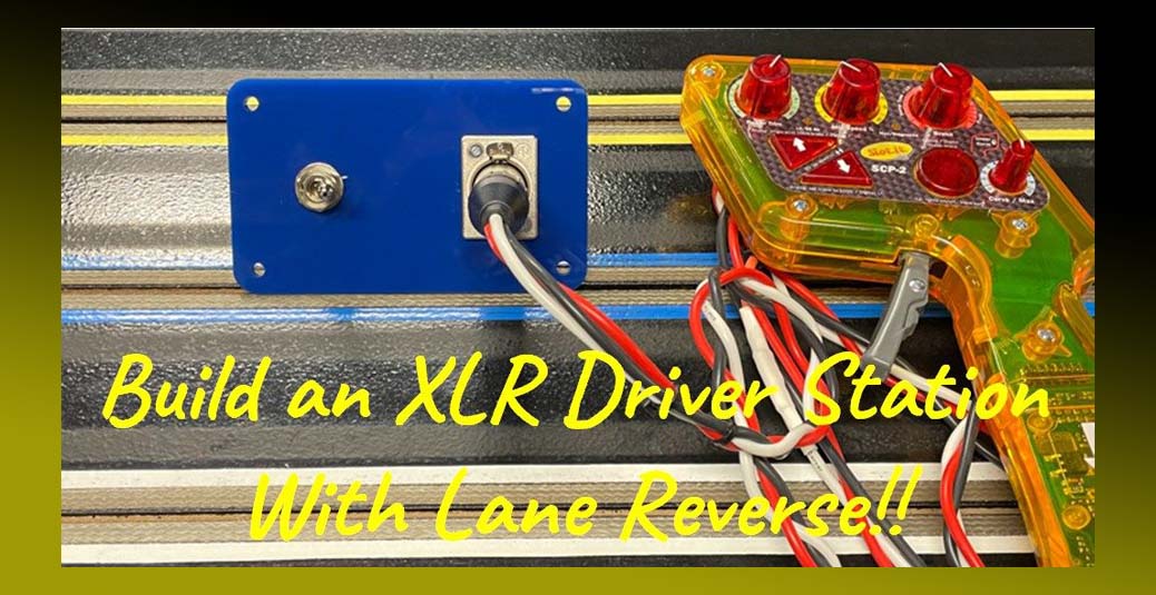
Since the inception of Slot Car Corner in 2006, we have offered a wide selection of slot car tracking wiring products and services including custom Driver Station fabrication services and high-quality, do-it-yourself Driver Station Kits. During this time, we have fabricated close to 1,000 driver stations for our customers worldwide. This article features our “XLR With Lane Reversing Switch” Driver Station Kit (SCC part number DS0220) shown below.
The driver station featured in this how-to article has a blue panel; however, kits with red, white, yellow, green, orange, purple and black are also available. This driver station is designed for controllers with male inline XLR connectors and features a toggle switch that lets you run your track in both directions. Note this driver station, when wired as recommended, is polarity independent – it will work with both resistor and electronic controllers.
You can purchase this kit by following this link.

The step-by-step instructions, and accompanying photos, are designed to make assembling this driver station kit as straightforward and painless as possible. No electrical knowledge is required to assemble this kit and most tools required are probably already in your toolbox. However, you will need a soldering iron (or soldering station) to solder three (3) wires to the XLR jack. Assembly typically takes about 60-90 minutes for the first kit and 45-60 minutes for each subsequent kit. We STRONGLY recommend reading through this entire document to become familiar with the steps BEFORE starting to assemble the kit. Additional resources including installation instructions, wiring diagrams, etc. are available on our website. Please refer to the “Additional Resources” section at the end of this article. As always, we are here to help – the “Contact” page on our website provides information about contacting us should you need further assistance.
Copyright Notice
This document, including all text, images and metadata, is Copyright © 2018 – 2020 by Slot Car Corner L.L.C.. All Rights Are Reserved. No part of this document may be reproduced, transmitted, or linked to in any form or by any means, electronic, mechanical, photocopying, recording, or otherwise, without PRIOR WRITTEN PERMISSION from Slot Car Corner L.L.C..
Tools
Caution: Be sure to read, understand and follow all manufacturer instructions concerning use of your tools. In particular, be sure to follow all safety instructions.
Here are the tools you’ll need to assemble the kit.
- #1 Phillips Screwdriver
- #2 Flat Screwdriver
- 9/16″ Wrench
- 7/32″ nut driver or wrench
- Wire crimping tool
- Wire stripping tool
- Ruler
- Hot glue gun (not shown)
- Soldering iron (not shown)
- Rosin flux (not shown)
- Rosin core solder (not shown)
- Heat gun or hair dryer (not shown)

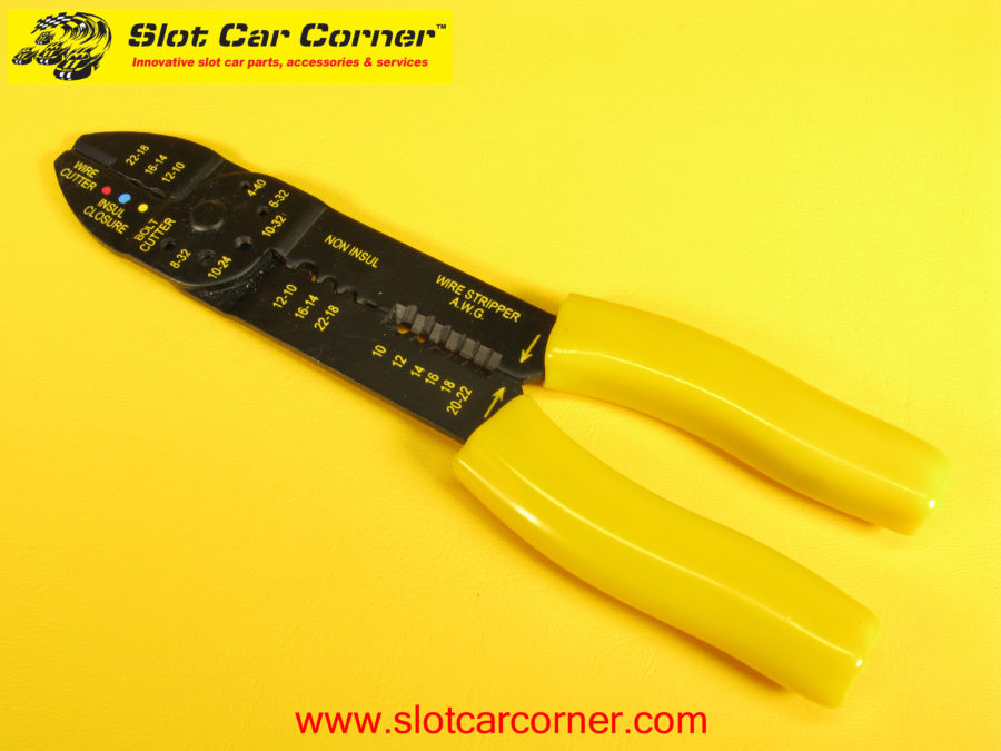
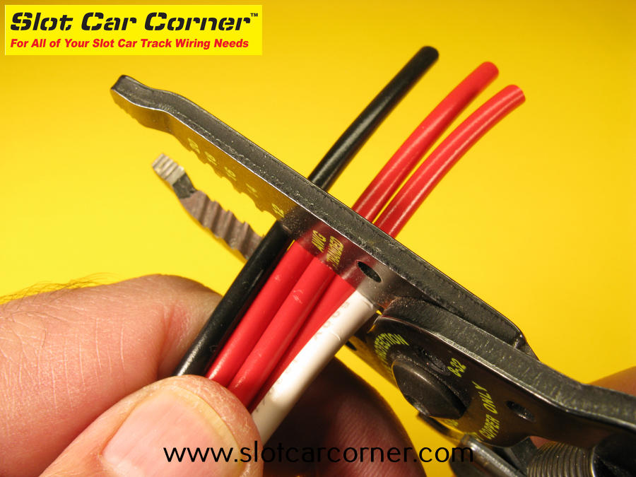
If you are purchasing a stripper/crimper tool for this project, a basic tool like the one in the picture below will strip wires, crimp terminals and cut wire without breaking the bank. Crimpers like this are readily available at most hardware, home improvement and automotive stores.
Wire
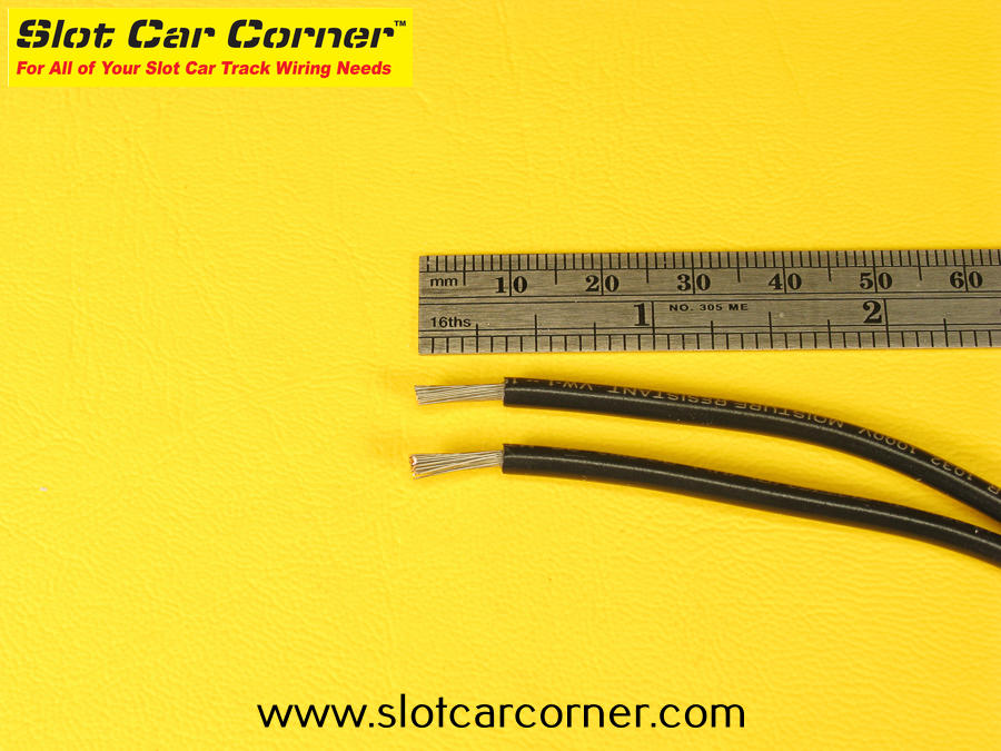
You will need some 14 AWG stranded copper wire to complete the kit. This wire is readily available at home improvement centers and automotive parts stores. If you use our recommended wire lengths, you will need the following (total) lengths for each insulation color: black – 36″, white – 24″ and red – 80″. Note these wire lengths/colors are for one (1) driver station. For convenience, we also offer high-quality Driver Station Wire specifically for this kit (SCC part number DWIRE-20 – shown below).

Step-by-Step Assembly Instructions
If you purchased our Slot Car Corner kit, the components are shown below. The kit includes a pre-drilled panel (available in multiple colors to match your track lane colors), panel mount XLR jack (bag on lower left), lane reversing switch (bag on lower right), spade connectors (bag on upper left), panel mounting hardware (bag on upper right) and an Assembly Diagram.
Tip: The Assembly Diagram included with the kit is also a useful reference – we suggest referring to it in addition to these instructions.

Let’s get started! First, carefully peel the protective covering off the front and back sides of the panel.

Installing XLR Jack on Panel
Before installing the XLR jack, make sure the panel is oriented as shown in the picture above. The larger hole on the right will be used to install the XLR jack. Note the two (2) smaller holes on the outside of the larger hole – they should be positioned at 11:00 o’clock and 5:00 o’clock as shown. The smaller hole on the left will be used to mount the lane reversing switch (discussed later in this write-up).


Insert the XLR jack into the larger opening. Square up the XLR jack to the side of the panel and secure using the two (2) machine screws and self-locking nuts. The release tab on the XLR jack should be facing up or away from you as shown in the accompanying picture. Do NOT overtighten – you can damage the mounting panel.


While the mounting screws/nuts will hold the XLR jack securely, we like to use some hot glue for added insurance. Turn the panel over and run a bead of hot glue around the circumference of the XLR jack where it meets the panel. Be CAREFUL not to put any hot glue near the release tab mechanism (see area at top of XLR jack in accompanying picture from roughly 11:30 to 12:30).

Set the three (3) pieces of shrink wrap aside for now.
Cutting/Crimping Wire for the Lane Reversing Switch
Tip: If you haven’t already done so, take a minute to download/print the Wire Cut / Strip Diagram and refer to it as we work through this section. Here is the link:
Wire Cutting / Crimping Diagram
Note: For the first set of black switch wires, we will break down cutting / stripping the wire and crimping terminals onto the wires in detail including plenty of accompanying pictures. This will be especially helpful to those of you following these instructions with little/no experience crimping electrical terminals on wires. For subsequent wires, we will just instruct you to “…strip such-and-such wire…” and then “…crimp such-and-such terminal onto the wire…”. If necessary, you can come back to the detailed descriptions and pictures provided here for the black wires.
We will start with the two black wires that will eventually be crimped together on one end. The shorter wire is 4″ long, the longer wire is 6″ long. The picture below shows the electrical terminals that will be crimped onto the wires. Note one end of the longer black wire does not have an electrical terminal – this is intentional (it will eventually be connected to the XLR jack).

Start by stripping 5/16″ from one end of the shorter (4″) black wire.

To ensure the female push-on terminal will slide over the bare wire properly, twist the bare wire strands slightly as shown in the picture below.

There should be no “loose” strands like those shown in the picture below.

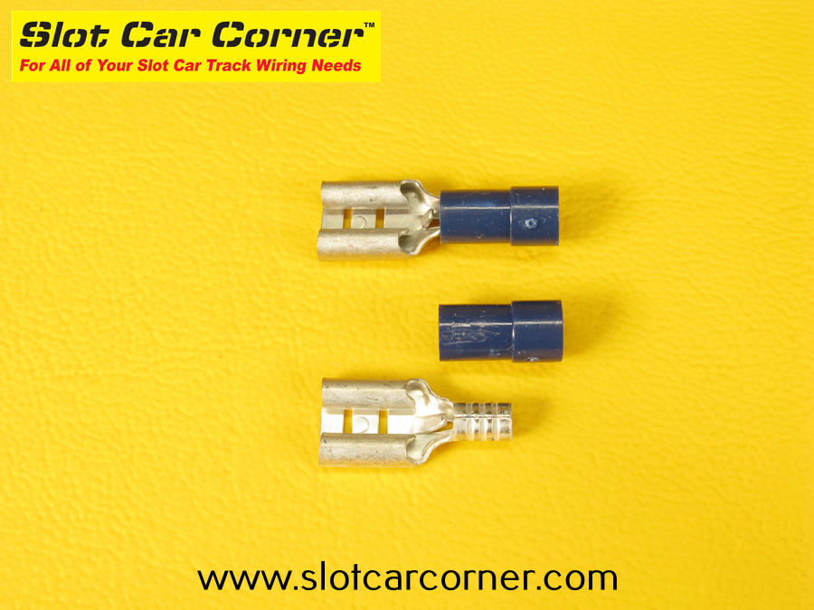
If you’re familiar with crimping insulated terminals, you can skip this paragraph. If you’re new to crimping insulated terminals, or just want a quick refresher, please read on. In the first picture below, we’ve “disassembled” an insulated electrical terminal like the ones provided in the kit. Note the “barrel” portion of the terminal that will be crimped to the wire does NOT extend all the way through the insulation. Therefore, it is VERY IMPORTANT to place your wire crimping tool over the portion of the insulation that covers the barrel. The second picture shows 2 crimps – one is crimped correctly and one is crimped incorrectly (and will fail). Take a few seconds to study these pictures and keep them in mind when crimping insulated terminals.
*** Tip *** While not required, we like to crimp and solder all terminals to wires. Soldering is like an insurance policy – if you have a marginal crimp, it will prevent the wire from working its way loose from the terminal.

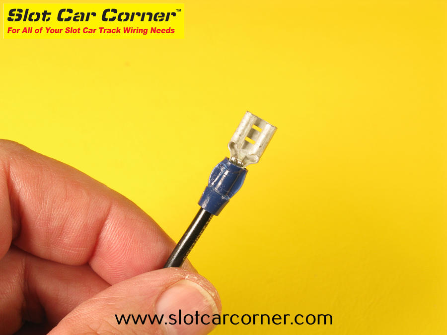
Insert a BLUE female push-on terminal onto the bare wire and crimp the terminal using the portion of your crimping tool designated for insulated terminals. Your crimp may look different depending on the crimping tool you use.
Next, strip 3/16″ of insulation from one end of the longer (6″) black wire as shown. Since this end of the wire will eventually be soldered to the panel mount XLR jack, there will be no electrical terminal crimped onto it.

Now we’ll join/connect the 4″ and 6″ black wires together. Start by stripping 3/8″ of insulation from the other end of both wires.
Hold the 2 wires beside each other as shown – note how the INSULATION is lined up on both wires.
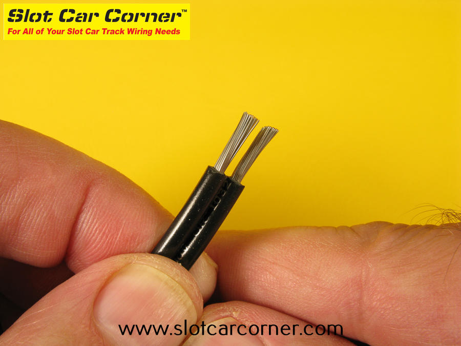

With the 2 wires lined up correctly as shown above, check the length of the bare portion of both wires. Both should be the same length (3/8″) – use your wire strippers and/or wire cutters to adjust the length if necessary.
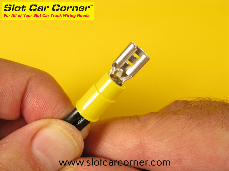
Holding the 2 wires FIRMLY with one hand (fingers) to ensure they stay properly aligned (see above), slip a YELLOW female push-on connector over the bare wires with your other hand (fingers). Make sure both wires are pushed through the terminal as far as possible AND the wires stay properly aligned. If the wires slip out of alignment, remove the wires from the terminal, re-align the wires and repeat this step.
Crimp the terminal using the area of your crimping tool designated for insulated terminals. The crimped terminal should look something like this – again, your crimp may look different depending on the crimping tool you use.
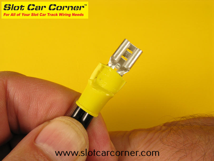
The two short black wires should look like the picture below. Don’t worry if your short and longer black wires are reversed – the important thing is the crimp on the yellow connector that holds them together. You can set them aside for now.

Now we’ll join/connect the 3-1/2″ and 24″ red wires together. Note the other end of the longer (24″) wire will not have a terminal crimped to it at this time. The picture below shows the electrical terminals that will be crimped onto these 2 red wires.
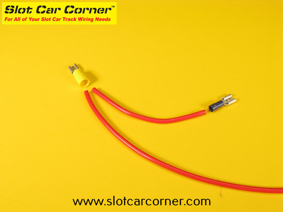
Note: If necessary, refer to the previous section for detailed instructions on stripping wire and crimping terminals when performing the steps described below.
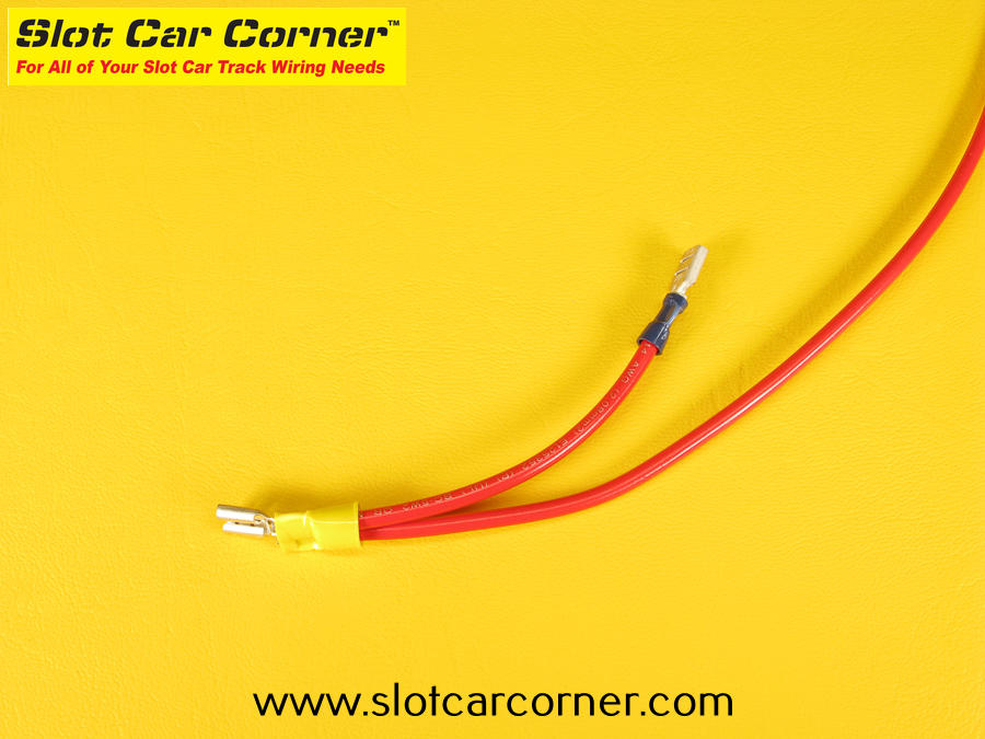
Strip one end of the short (3-1/2″) red wire and crimp a BLUE female push-on connector onto it.

Remove (strip) 3/8″ of insulation from one end of the long (24″) red wire and the other end of the short (3-1/2″) red wire. Align the wires, and crimp a YELLOW female push-on connector as shown below.

The 2 red wires should now look something like this. Again, don’t worry if your wires are reversed. You can set them aside for now.
Next, cut a 24″ length of red wire and a 24″ length of black wire. Strip one end of each wire and crimp a BLUE female push-on connector onto each wire.

Wiring the Lane Reversing Switch
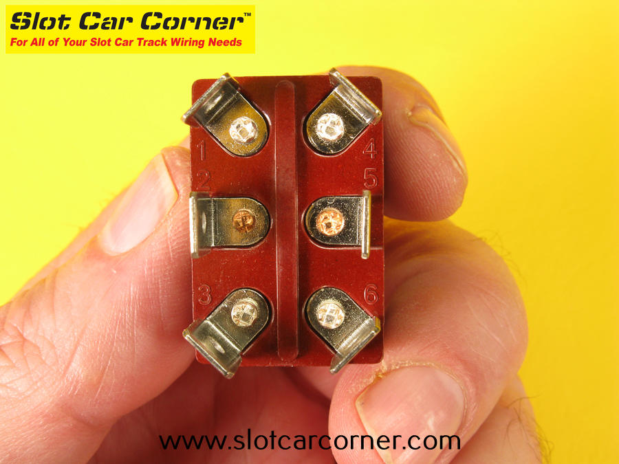
Now that you’ve cut and crimped all of the wires needed for the lane reversing switch, it’s time to actually wire up the switch. Start by carefully examining the bottom of the switch. Notice the numbers 1 – 6 embossed in the switch housing. Each number corresponds to one of the switch’s 6 “blade” terminals. We’ll refer to these numbers in the subsequent steps to identify the switch terminal a given wire terminal should be connected to.
Slide the YELLOW female push-on terminal that connects the 2 short black wires onto the terminal blade labeled “6” as shown below.
CAUTION: If you inadvertently slide a push-on terminal onto the wrong switch terminal, DO NOT pull on the wires to remove it! Instead, grasp the crimped portion of the push-on terminal and carefully remove it from the switch.

Slide the BLUE female push-on terminal on the other end of the shorter (4″) black wire onto the terminal labeled “1” (diagonally opposite from terminal “6”).

Slide the YELLOW female push-on terminal that connects the 2 red wires onto the terminal blade labeled “3” as shown below.

Route the BLUE female push-on terminal on the other end of the short red wire UNDER the black wire that is already in place and slide it onto the terminal labeled “4”.
Just 2 more wires to connect! Next slide the BLUE female push-on connector on the 24″ single black wire onto the switch terminal labeled “5”.
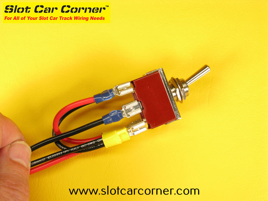
Finally, slide the BLUE female push-on connector on the 24″ single red wire onto the switch terminal labeled “2”.
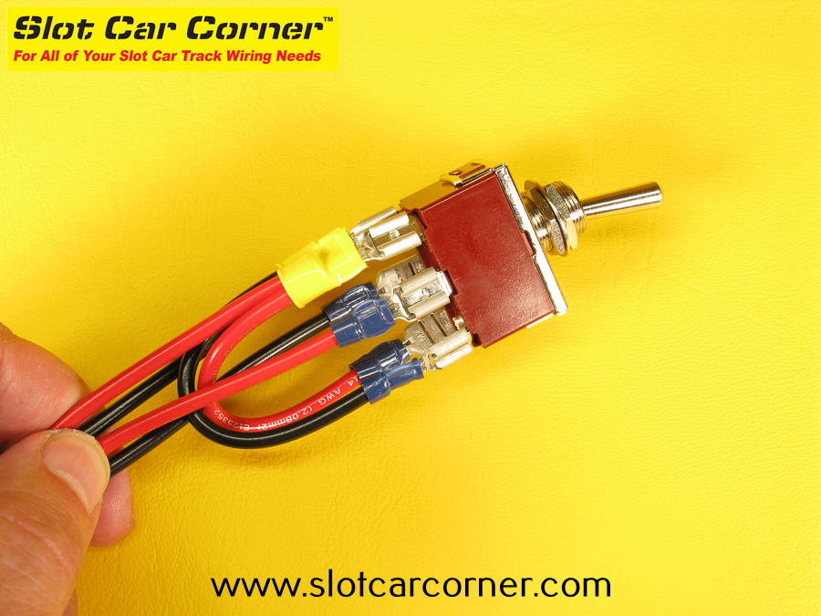
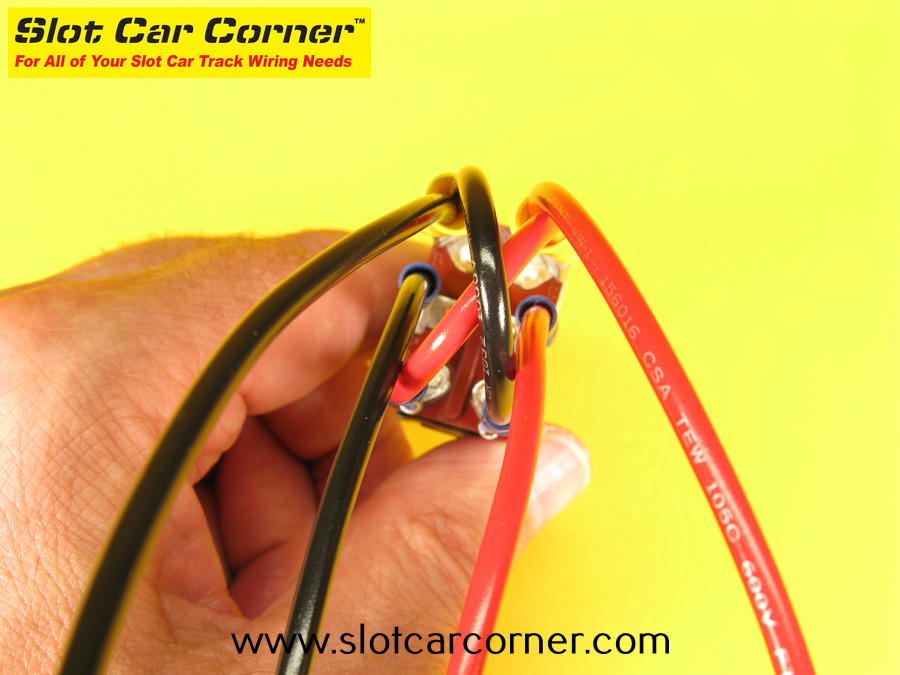
Here’s a picture of the underside of the switch with all wiring installed. For reference, terminal “6” (double-black wires) is in the upper left corner). Note the distinctive “X” formed by the short red and black wires.
Installing Lane Reversing Switch on Panel
Congratulations! You’ve completed the most difficult part of the driver station assembly (it wasn’t really difficult – just a lot of steps). Now it’s time to mount the switch to the panel. Your driver station will really start coming to life from here on out.
We’ll start by mounting the switch that you just wired to the panel. If you haven’t already done so, remove the retaining nuts (2x) and mounting washer (1x) from the threaded mounting bushing on the switch.

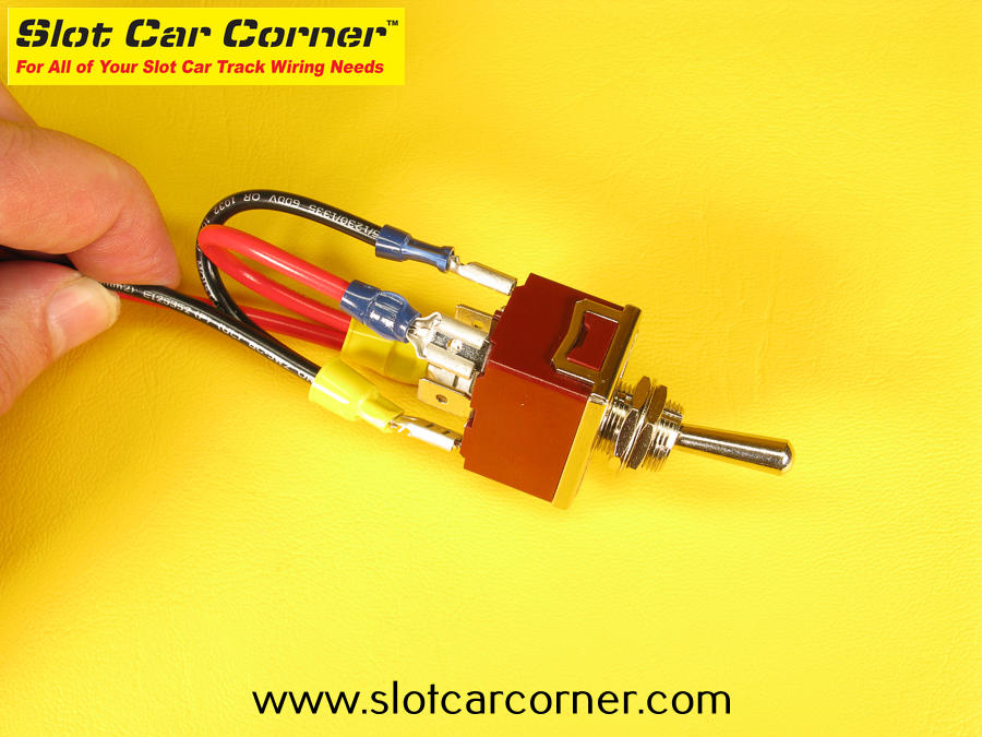
With the XLR jack on the right side of the panel as shown, insert the threaded switch mounting bushing through the bottom of the panel. IMPORTANT: Note the orientation of the switch – from L-R there is a single red wire, single black wire and double black wire on the side of the switch closest to you. From L-R these are switch terminals “4”, “5” and “6”. If your switch is not oriented like this, rotate it 180 degrees and check again.

Hold the switch housing on the underside of the panel with one hand. Insert the mounting washer over the mounting bushing with your other hand.

Thread one (1) of the retaining nuts onto the mounting bushing as far as you can by hand.

Double check to make sure the switch is still oriented correctly in relation to the panel (refer to earlier step if you are unsure). Using a 9/16″ wrench, carefully tighten the retaining nut until you just feel a little resistance. Do NOT overtighten – you can damage the switch and/or mounting panel.

Turn the switch until the “long” side of the switch is parallel with the long edge of the mounting panel as shown. SNUG down the locknut to prevent the switch from turning in the panel. DO NOT overtighten.


Run a bead of hot glue where the switch housing meets the panel – the bead should run along 3 sides of the switch (do NOT run a bead of glue along the long edge of the switch housing that is closest to the long edge of the mounting panel).
The bead of hot glue should run along both “long” sides of the switch (only one is visible in this picture) and the short side of the switch closest to the XLR jack as shown below.

Thread the second retaining nut onto the switch mounting bushing – when it makes contact with the retaining nut already installed, tighten JUST THE TOP NUT slightly so it acts as a “jam nut”. This will prevent both nuts from loosening.

Wiring the XLR Jack
*** IMPORTANT *** While there is no universally accepted standard for the XLR jack “pinout”, most tracks using XLR connectors have adopted the following convention.
- Pin 1 – Black
- Pin 2 – White
- Pin 3 – Red
If you plan to race with a club that uses XLR connectors, check with other club members to verify the XLR pinout used on their tracks.
Now that the lane reversing switch and XLR jack have been mounted, we’re ready to make the wiring connections to the XLR jack.
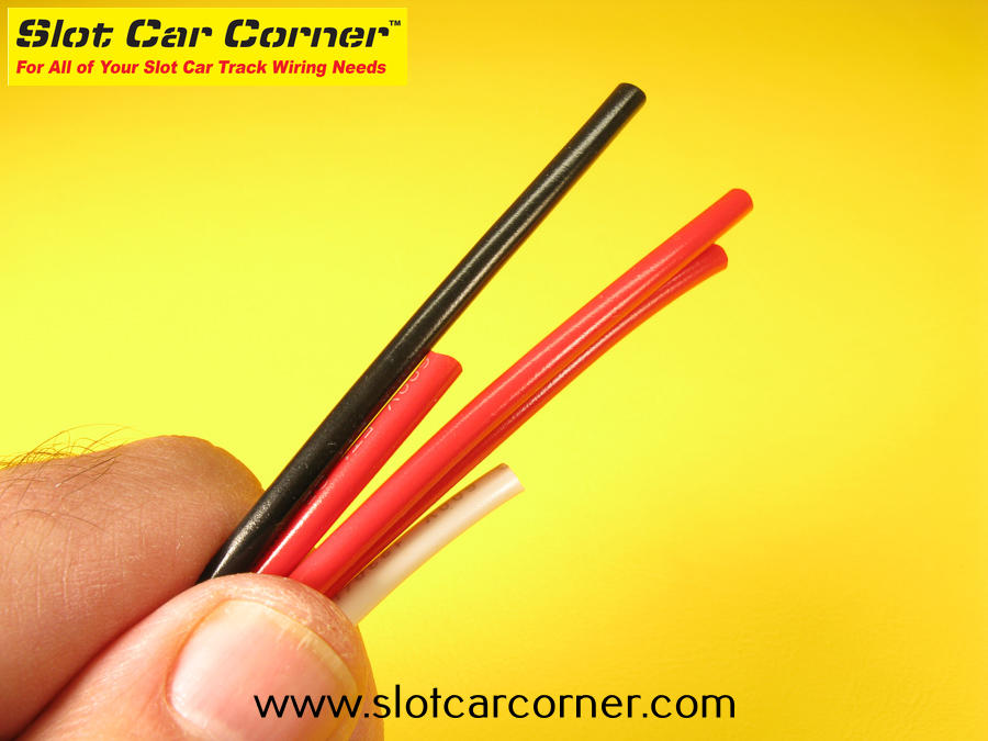
Start by cutting a 24″ length of white wire and a 24″ length of red wire. Strip 3/16″ of insulation from one end of each wire.

Use a toothpick or small paintbrush to “dab” a small amount of ROSIN flux in each of the three (3) solder pots on the XLR jack as shown below. *** CAUTION *** Do NOT use acid flux (commonly used for plumbing applications)!! Acid flux will eventually corrode the wires causing the solder joints to fail.

Using your soldering iron, “tin” each of the solder pots on the XLR jack with a small amount of rosin core solder. Tinning the solder pots will make it easier to solder wires to each of the pots in a later step. Soldering instructions are beyond the scope of this how-to article. The basic steps to tin each solder pot are as follows:
- Place the tip of your soldering iron on the back of the solder pot as shown below.
- Position your rosin core solder in the solder pot as shown below.
- Once the solder starts to “wet” (flow), remove the solder – you just need a little bit.
- Wait a second, and then remove the soldering iron tip.
*** CAUTION *** Use only rosin core solder – do NOT use acid core solder.

The tinned solder pots on the XLR jack should look something like this.

14 AWG stranded wire is a tight fit into the solder pots on the XLR jack. To help ensure a proper fit, twist the bare wire strands together as tightly as possible. Check to ensure there are no loose strands.


Next, “tin” the bare wire – this will make it easier to solder the wire to the solder pot on the XLR jack (described in an upcoming step). Start by using a toothpick or small paintbrush to apply some rosin flux to the bare wire. Then use the tip of your soldering iron and a small amount of rosin core solder to tin the wire as shown as shown. When tinning wire, you only need to just barely coat the wire with solder – don’t overdo it! Be careful to ensure the wire strands stay tightly twisted together.

Before proceeding, make sure you have slipped a short piece of heat shrink included with the kit onto the black wire and slide it as far away from the solder pot as possible.


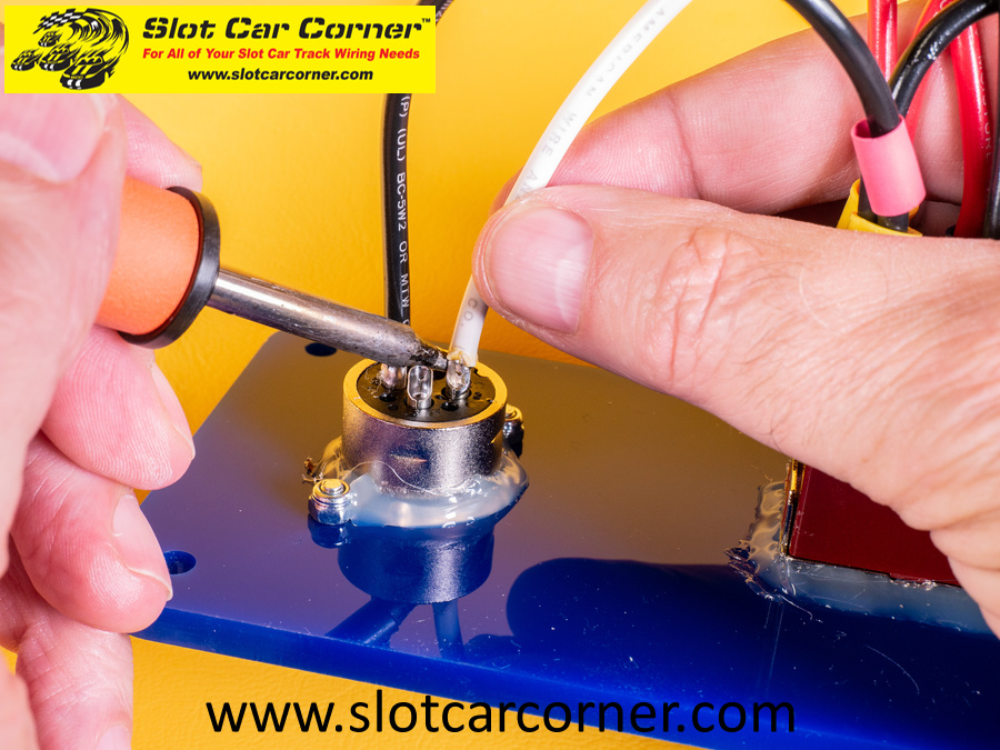
Now we’re ready to solder the black wire to the solder pot labeled “1” on the XLR jack. You will find the number “1” embossed in the XLR jack housing. Position the tinned end of the black wire into the solder pot as shown. *** IMPORTANT *** DO NOT try to force the wire into the solder pot!
*** CAUTION *** Did you remember to slide a piece of heat shrink over the black wire? Slide it on as far as possible for now so it doesn’t inadvertently shrink while soldering the wire.
*** Tip *** If you are new to soldering or are soldering wires to the solder pots for the first time, we strongly recommend practicing the steps described in the next paragraph a few times with the soldering iron turned OFF.
Position the tip of your soldering iron on the back side of the solder pot as shown. Do NOT try to force the wire into the solder pot! When the soldering iron heats the solder pot sufficiently, the solder you placed in the solder pot earlier along with the solder on the end of the wire will melt. Once the solder melts, you can insert/slide the wire all the way down into the solder pot. Once the wire is firmly seated in the solder pot, wait a second or two and then remove the soldering iron. Continue holding the wire in place for several seconds to allow the solder to setup.

Now repeat the steps described above for the black wire to tin the end of the white wire and solder it to the solder pot labeled “2”. You don’t have to worry about the heat shrink since you can slide it over the other end of the white wire once you have soldered the wire to the XLR jack.
Now repeat the steps described above for the black wire to tin the end of the red wire and solder it to the solder pot labeled “3”. You don’t have to worry about the heat shrink since you can slide it over the other end of the red wire once you have soldered the wire to the XLR jack.

Slide the heat shrink on each wire so it covers the solder pots as shown. Be sure each piece of heat shrink is resting on the XLR housing as shown.

Use a heat gun or hair dryer to “shrink” the heat shrink in place. They should look something like the picture below.

Use tie wraps included in the kit to organize the wires using the picture below as a guide.

Trim the tie wraps to length.

Next we will use the wire cutters to trim the ends of all five (5) long wires to the same length.

Strip each of the wires and crimp a spade terminal onto the end of them as shown.
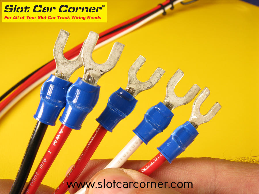
Congratulations – your completed driver station is ready for installation!!

Additional Resources
Please visit the XLR Plus Lane Reverse Switch Driver Station product page on our website for a mounting template, installation instructions and a generic slot car track wiring diagram for this driver station. We hope you found this how-to article useful.
Thank you!
-Steve
