You Can Do This!
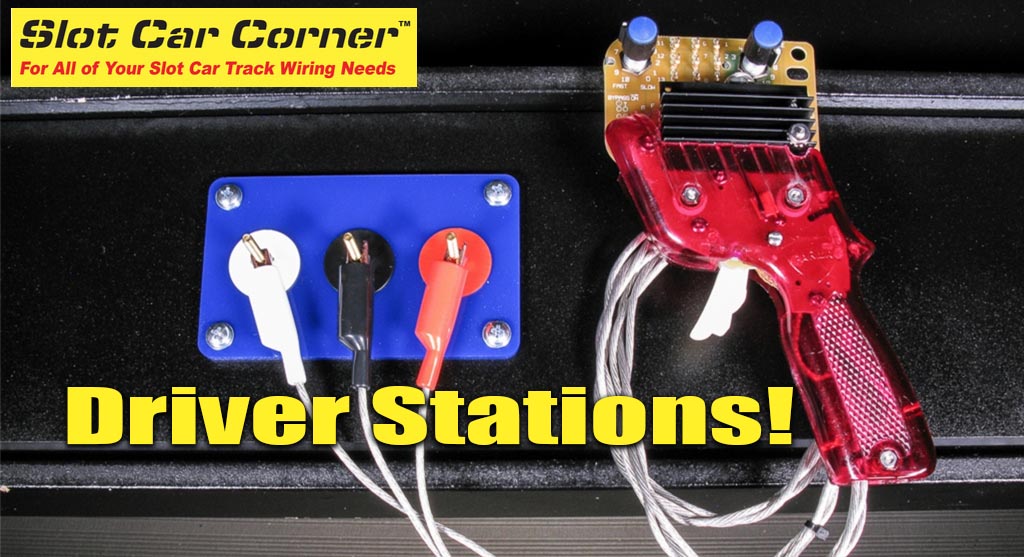
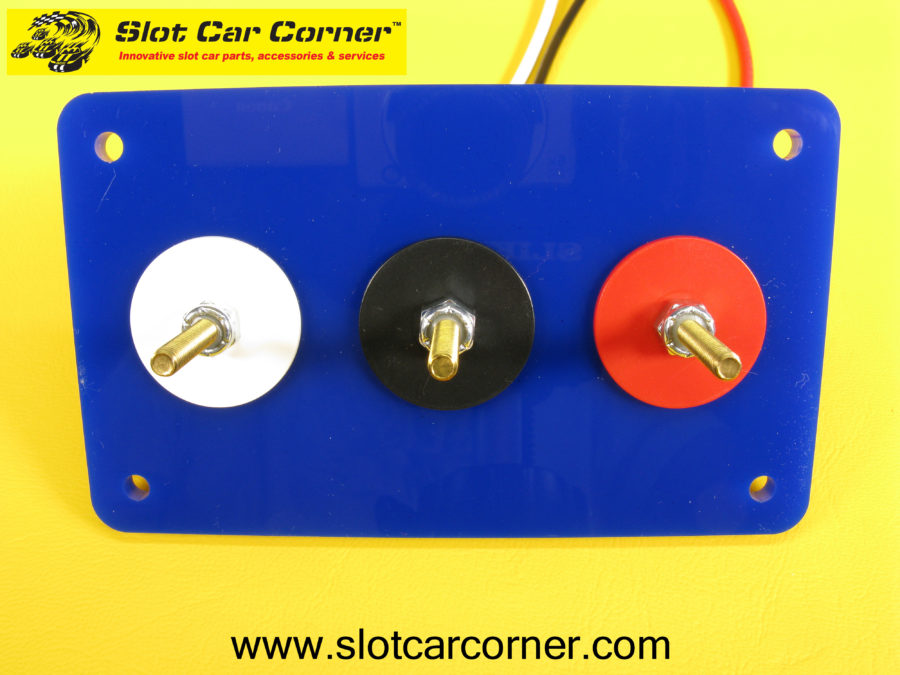
Since the inception of Slot Car Corner in 2006, we have offered a wide selection of slot car tracking wiring products and services including custom Driver Station fabrication and high-quality Driver Station Kits. During this time, we have fabricated close to 1,000 driver stations for our customers worldwide. This article features our “3 Post Commercial Style Hookup” kit (SCC part number DS-0100) shown below. This driver station is designed for controllers with alligator clips.
The step-by-step instructions, and accompanying photos, are designed to make assembling the driver station kit as straightforward and painless as possible. No special skills, tools or electrical knowledge are required to assemble this kit – assembly typically takes 30 – 45 minutes. We recommend reading through this entire document to become familiar with the steps BEFORE starting to assemble the kit. If you’d like more information about this kit, or would like to purchase the kit, please click this link. Additional resources including installation instructions, wiring diagrams, etc. are available on our website. As always, we are here to help – the “Contact” page on our website provides information about contacting us should you need further assistance.
Copyright Notice
This document, including text and images, is Copyright © 2018 by Slot Car Corner L.L.C.. All Rights Are Reserved. No part of this document may be reproduced, transmitted, or linked to in any form or by any means, electronic, mechanical, photocopying, recording, or otherwise, without prior written permission of Slot Car Corner L.L.C..
Tools
Caution: Be sure to read, understand and follow all instructions concerning use of your tools. In particular, be sure to follow all safety instructions.
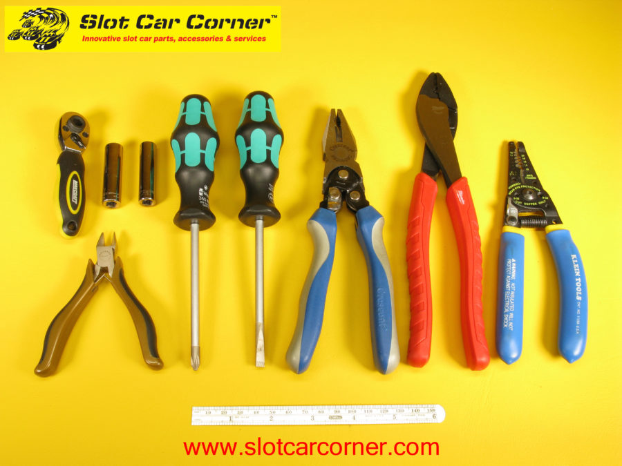
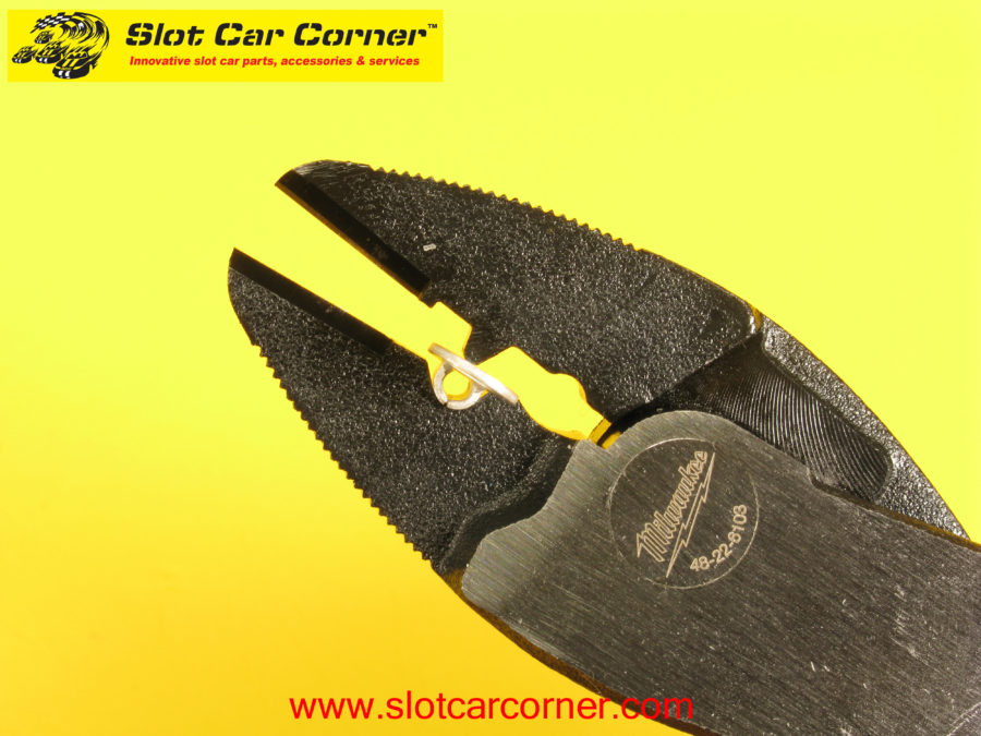
Here are the tools you’ll need to assemble the kit. While not required, using a small ratchet and deep well sockets (11/32” and 3/8”) will make securing the posts to the panel much easier. Wrenches will work, they’ll just take a little longer (and test your patience…). The rightmost tool (blue handles) is a wire stripper/cutter. The tool next to it (red handles) is a terminal crimper / wire cutter.
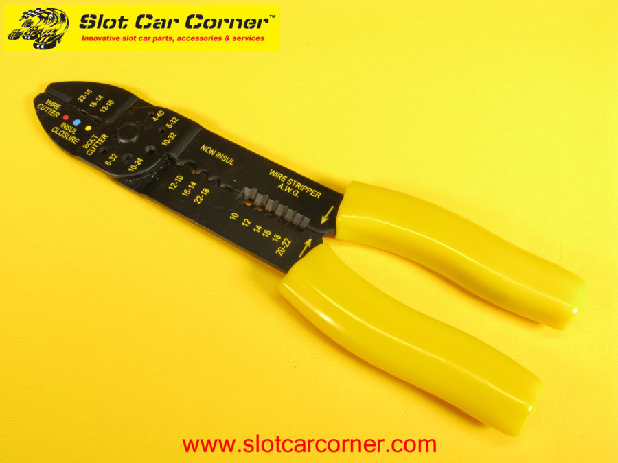
If you are purchasing a stripper/crimper tool for this project, a basic tool like the one in the picture below will strip wires, crimp terminals and cut wire without breaking the bank.
Wire
You’ll also need some 14 AWG stranded copper wire to complete the kit. We recommend 18” long wires but you can make them longer if necessary. We will use wire with black, white and red insulation (to match the driver station hookups). This wire is readily available at home improvement centers and automotive parts stores. For convenience, we also offer Driver Station Wire pre-cut to the recommended 18” lengths (SCC part number DWIRE-10 – shown below).

Step-by-Step Assembly Instructions
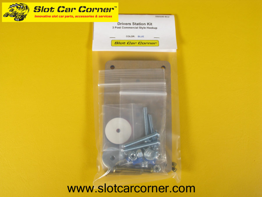
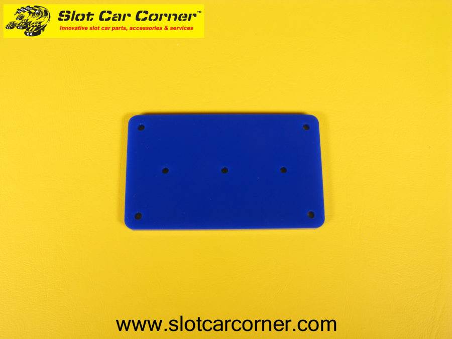
If you purchased our Slot Car Corner kit, the components are shown below. The panel (center) and small bag on the left contains the components we’ll be focusing on in this article. The Assembly Diagram is also a useful reference – we suggest referring to it in addition to these instructions. The hardware in the small bag on the right will be used to mount the completed Drivers Station to your track.

Let’s get started! First, carefully peel the protective covering off the front and back sides of the panel.

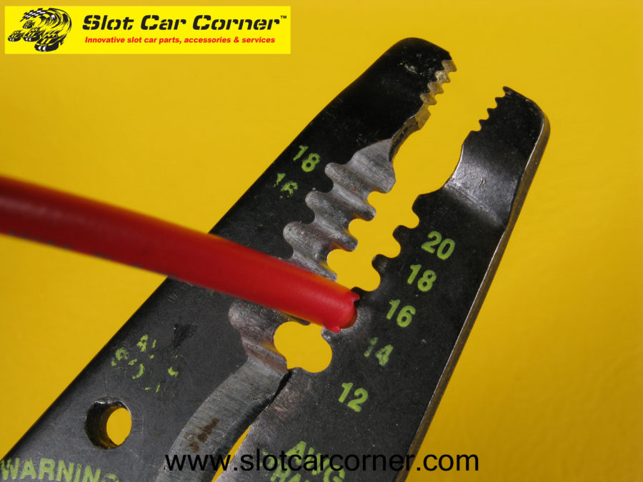
Next, strip 5/16” of insulation off ONE end of each wire. Do NOT strip insulation off the other end of the wires at this time.

To ensure the ring terminal will slide over the bare wire properly, twist the bare wire strands slightly as shown in the picture below.
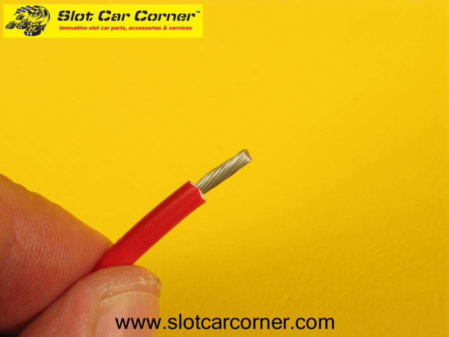
There should be no “loose” strands like those shown in the picture below.

Insert a ring terminal over the bare insulation on one of the wires – note there should be about 1/16” of bare wire that protrudes from the terminal barrel. If necessary, remove (strip) more insulation or trim off excess bare wire before crimping the terminal.
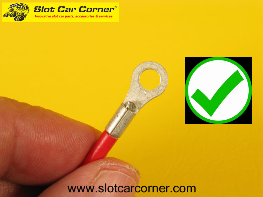
Be sure the depth of the bare wire is correct and there are no “loose” strands.


Using your wire crimping tool, position the barrel of the ring terminal into the crimper. Be sure to use the crimping area designated for non-insulated terminals. Some crimping tools will also have different positions for the size terminal (14-16 AWG) being used. Note the position of the “tooth” that will make an indentation in the terminal – it is on the “back” side of the terminal barrel, 180 degrees from the seam. Make sure the bare wire is inserted as far as it will go into the terminal barrel. Squeeze the crimping tool firmly to crimp the terminal to the wire. Repeat this step for the remaining two (2) wires.

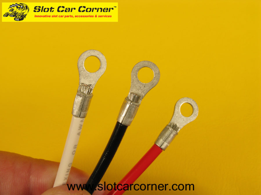
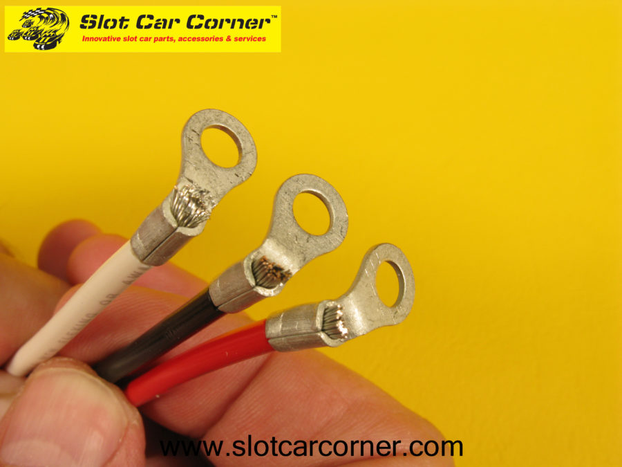
The accompanying images show the front and back of the crimped ring terminals. Note the crimp indentation shape (right picture) – your shape may be different depending on the crimping tool you use.

Position the ring terminal into a pair of lineman or slip-joint pliers as shown below. A vise could also be used for this step.

Before proceeding, study the pictures below VERY CAREFULLY! SLOWLY and carefully bend the ring AWAY from the wire as shown until there is roughly a 90-degree bend as shown.


Repeat the steps above for the remaining two (2) wires. Your ring terminals with 90-degree bends should look like those in the picture below.
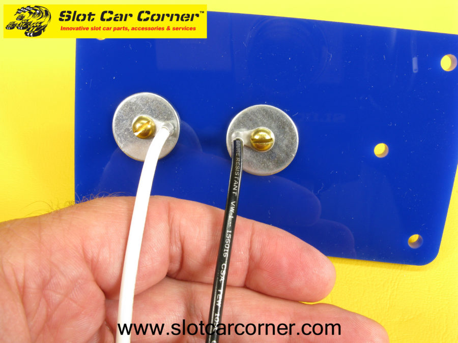
Now let’s attach the wires/posts to the panel. We will start with the white wire and insert a brass machine screw through the ring as shown below.
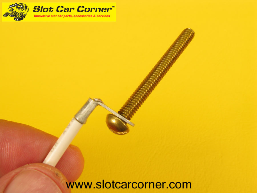
Next, insert a metal washer over the brass machine screw.

Now insert the brass machine screw through one of the “end” holes as shown. Since this panel is symmetrical, it doesn’t matter on which end you start.

On the top of the panel, insert the white plastic washer over the machine screw. Next, thread a locknut onto the end of the machine screw.

Hold the brass machine screw in place with a flat blade screwdriver while tightening the locknut with a 11/32” wrench. A deep well 11/32” socket will make this task MUCH easier/faster if you have one.
CAUTION – Use care not to overtighten the locknut – it just needs to be snug. Overtightening the locknut could damage the plastic washer and/or panel.
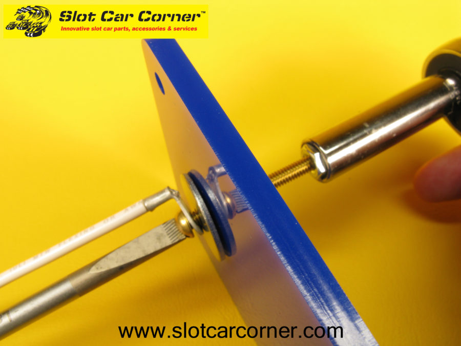
Here’s what the white wire/post should look like.


Next, install the black wire in the center panel hole using the same steps described above for the white wire.

Finally, install the red wire in the remaining hole using the same steps described above for the white and black wires.
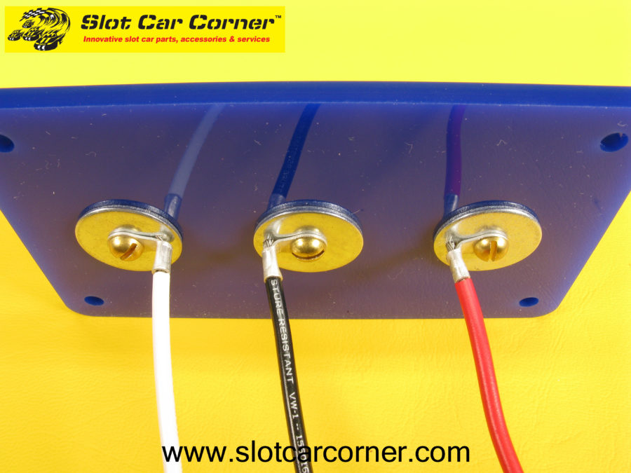
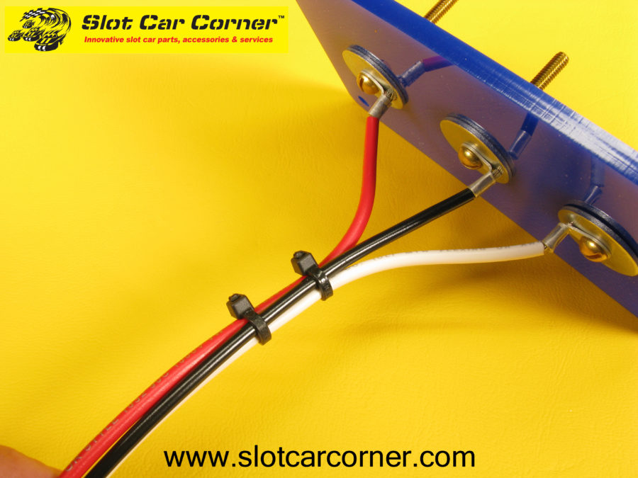
Use the tie wraps included in the kit to help secure and organize the wires.

Use wire cutters to trim the ends of all 3 wires so all wires are the same length.


Strip 3/8” of insulation from the end of each wire as shown. Crimp a spade terminal onto each wire as shown. Be sure to use the portion of your crimping tool designated for insulated terminals.


Congratulations – your completed drivers station is ready for installation!!
Additional Resources
Please visit the 3-Post (Alligator Clip) Driver Station product page on our website for a mounting template, installation instructions and a generic slot car track wiring diagram for this driver station.
-Steve
