
Repairing a Broken Body Post
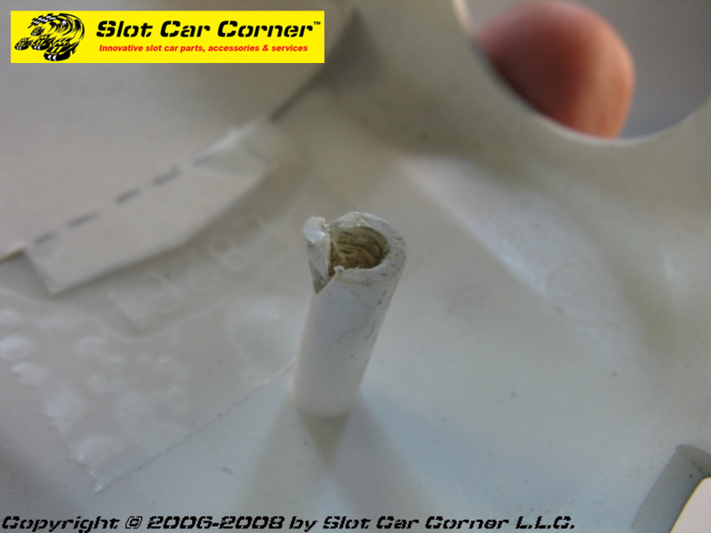
How many of your slot car bodies see limited use (or can no longer be used at all) because of broken/damaged body posts like the one in the accompanying picture? You don’t have to race 1/32 slot cars very long to experience some sort of problem with the body mounting posts. While in extreme cases they may break right off the body, more often they crack or split. Body post cracking and splitting can have many causes – some common examples include using the wrong screw (too large in diameter and/or the wrong thread), screw misalignment when inserting, over-tightening the screw, or excessive screw insertion/removal cycles. Whatever the cause, repairs typically involve replacing all or part of the post, reinforcing the existing post or filling/retapping the existing screw hole. In all cases, there is a good chance the repaired post will eventually fail again. This write-up will demonstrate one approach to repairing body posts. Keep in mind this is not the only way to repair a body post nor are we claiming it’s the “best” way. We’ve used this approach for years with very good results.
For the repair, we’ll use one of our Slot Car Corner Body Post Repair Kits as shown below. We offer various kits – this is the #2 kit with panhead screws. Note this kit requires soldering; however, we also offer kits with the inserts pre-soldered into the sleeves. For convenience, you can use the link below to find these kits in our online store.
Click Here ==> SCC Body Post Repair Kits

Let’s take a minute to look at the kit. The inserts accept the included M2 screws which will replace the stock body screws to secure the body to the chassis. Note the screws feature a shank with a smooth section to promote better body “float”. The insert is designed to be secured (soldered) into a brass tube or sleeve. In addition to durability, this system offers another important advantage over plastic body posts and (metal) body screws. With stock body posts, even posts that are in good condition, body screws have a tendency to work themselves loose and in some cases, fall out altogether. In either case, the car’s handling and overall performance is adversely affected (in extreme cases, the car may not be able to continue racing). Threadlockers (e.g. , Permatex, Loctite) are one potential solution; however, many ordinary threadlockers are not plastic compatible. While there are special threadlockers designed specifically for metal-to-plastic applications (e.g. Loctite 425), they are generally very expensive. In contrast, the inserts shown here along with the mounting screws offer a metal-to-metal mounting system – this allows ordinary medium-strength (removable) threadlockers to be used to keep the body mounting screws exactly where you want them.
Step-by-Step Installation Instructions
What follows are step-by-step instructions which describe and show how to repair body mounting posts for a 1/32 RTR car. In general, this approach works best with cars/bodies having longer body posts – ideally at least 7/16″ (11mm) long. The example uses an older-style Scalextric Nascar for illustration; however, the same techniques can be used on a wide variety of 1/32 cars. The “sleeves” used to secure the insert in this article are made from brass tubing. Brass tubing provided in the kit can also be “nested” to achieve different inner diameters to fit over the body post being repaired.
Caution: Always wear safety glasses and follow all manufacturer’s instructions and safety guidelines when using hand or power tools.
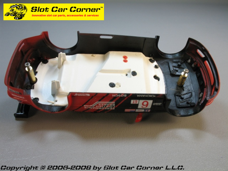
Here is the broken body mounting post we will be repairing. Again, this is an older-style Scalextric Nascar body.

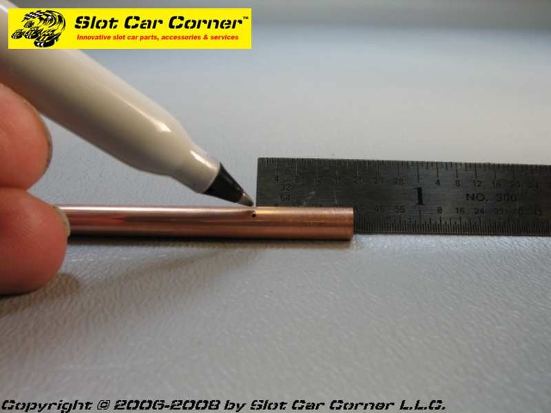
First measure the length of the body post. Note this body post is mounted at an angle to the underside of the body – therefore, one side is longer than the other. Be sure to measure the longer side. In this case, the post is about 9/16″ long.

For this repair, I have chosen to use some 3/16″ brass tubing included in the SCC Body Post Kit because it fits perfectly over the stock body post. Ideally the sleeve will fit snug but not so snug that you risk further damage to the post while sliding the sleeve on/off.
- If you are using the SCC Body Post Repair Kit #2 like the one in this article, measure a length of tubing about 1/32″ shorter than the measurement you took in the last step. The 1/32″ is necessary to compensate for the height of the insert’s mounting flange.
- If you are using the SCC Body Post Repair Kit #3 with pre-soldered inserts/sleeves, use the actual length of the body post to mark and cut the tubing.
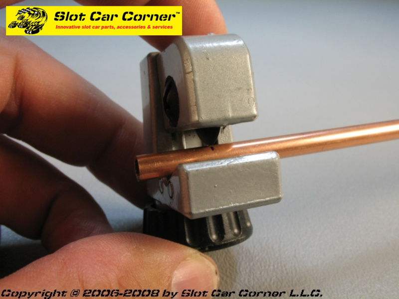
Carefully cut the tubing – here I am using a tubing cutter; however, a cut-off wheel mounted to a Dremel or small hobby saw (with the appropriate blade for the material you are using) could have been used as well. Carefully remove any burrs from the tubing where is was just cut. For the 3/16″ tubing be used in this example, a 5/32″ drill bit and a small file makes it easy to remove the burrs.

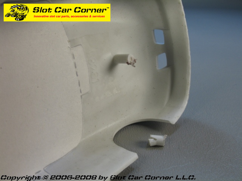
This next step will vary depending on the car/body post being repaired. If the stock body post is too long, it may interfere with the threaded brass insert that will be soldered inside the brass sleeve. On the other hand, you want to leave enough of the body post so you have something to secure the brass sleeve to. The portion of the body post that you leave will also help align the brass sleeve properly so it lines up with the chassis mounting hole. For this body post, I removed about 1/4″ of material as shown.
Use a sanding stick (or sandpaper) the remove any excess plastic flashing which may be present from the cutting operation. Apply a slight chamfer to the end of the post to make it easier to slide the tubing over.
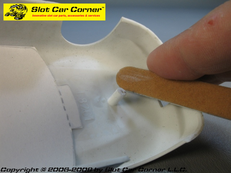
Carefully test fit the sleeve over the remaining portion of the body post as shown. You can sand the body post “stub” if there is too much resistance when trying to slide the sleeve in place. We are only concerned with ensuring the brass sleeve slips over the body post at this point. We’ll fine tune other aspects of the fit in subsequent steps.
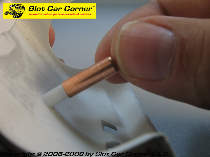
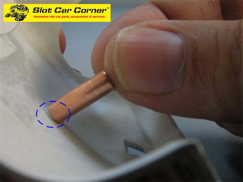
Pay particular attention to where the sleeve meets the body (circled area). Because this body post is attached to the body at a slight angle, it will be necessary to modify the “bottom” of the sleeve to match this angle.
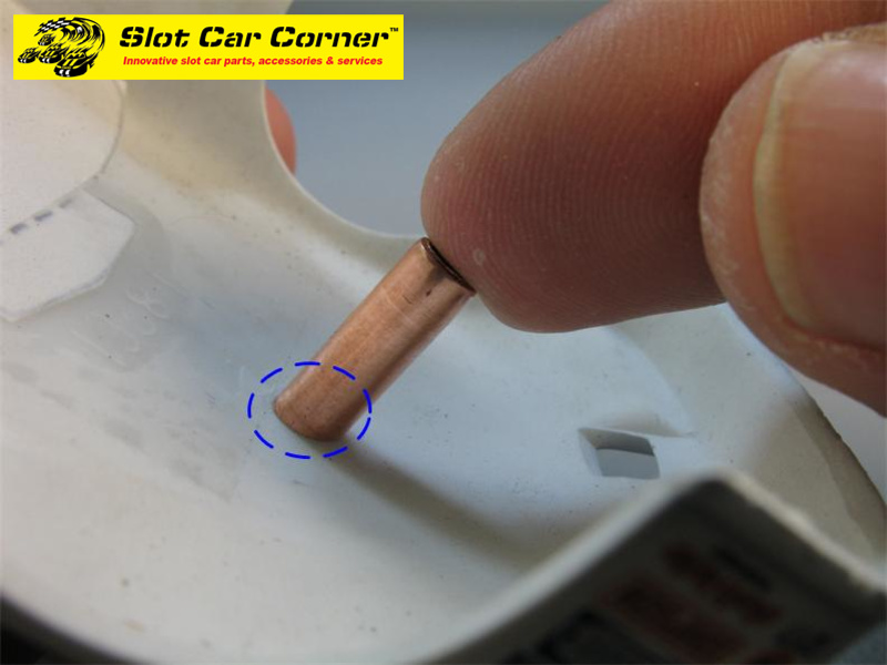
Here is the modified sleeve (circled area) – a small file was used to adjust angle of the brass sleeve where it meets the body. This may take some trial-and-error. As the picture shows, the bottom of the sleeve is now perfectly flush with the bottom of the post where it meets the body.
Before proceeding, double-check the new post length and adjust if necessary. Do NOT secure the sleeve to the post yet.

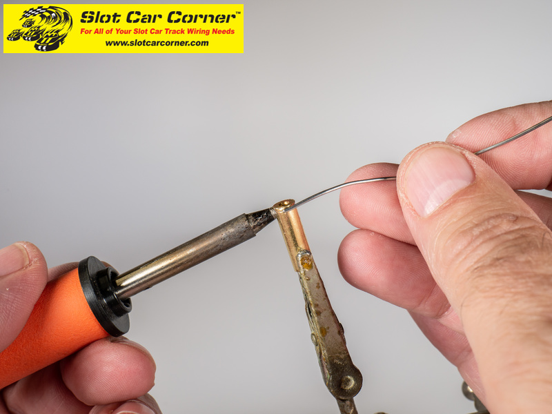
Remove the brass sleeve from the body post “stub” and solder the brass insert into the top of the sleeve.
Tip: A pair of “helping hands” makes it easier to position and hold the sleeve and insert while keeping both hands free for soldering.
Carefully install the sleeve back onto the body post “stub”. Test fit the body onto the chassis to ensure the sleeve is the right length and lines up with the mounting hole in the chassis. When you are satisfied with the fit, glue the sleeve onto the body post “stub”. In this example, we used a couple of drops of rubberized superglue; however, a bead of epoxy, Goop, etc. (or your favorite adhesive) could also be used to secure the sleeve.
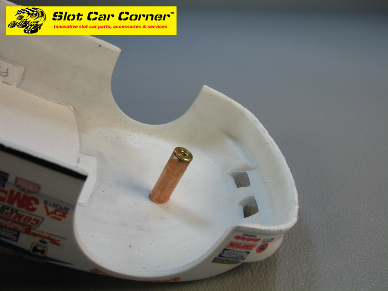
A small drop of low or medium strength threadlocker can be used to prevent the body post screw from working its way loose.

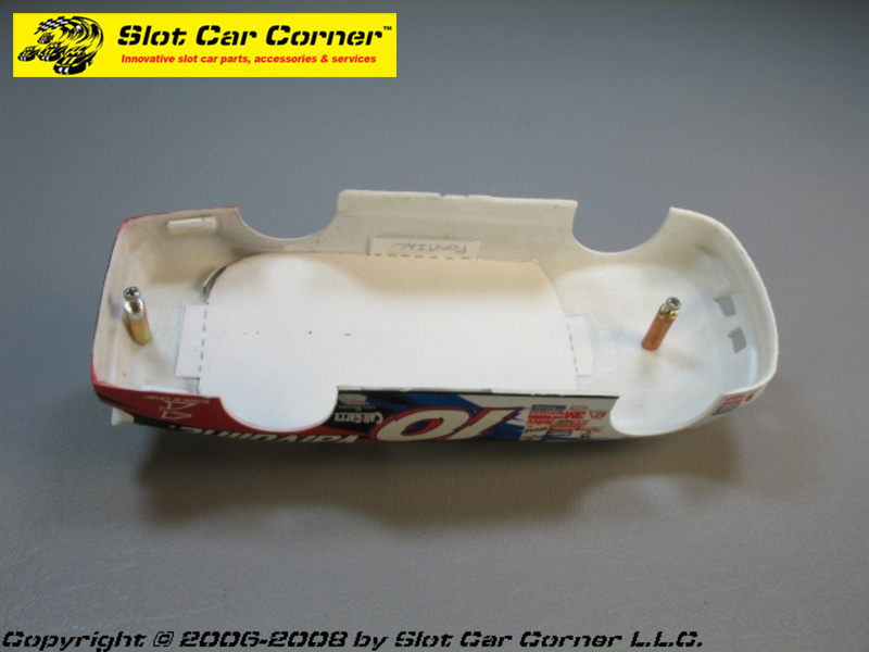
We went ahead an repaired the rear body post for this car using the same steps described above.
Here are some additional example of body posts repaired using the SCC Body Post Repair Kits and techniques described in this article.
Scalextric Porsche 911

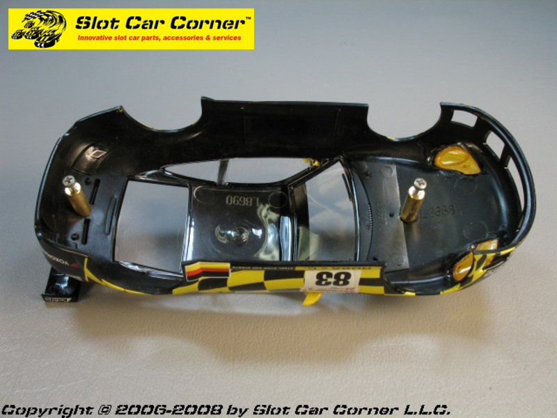
Ninco BMW M3

Slot.it Porsche 956


We hope this article helps bring new life to your slot cars sitting on the shelf because of cracked/broken body posts!
Steve
