Page 1 of 1
Wiring a 2 in 1 controller station

Posted:
Mon Sep 29, 2014 5:03 pmby Retro Racer 44
I am building a small 2 lane oval for my grandkids to race on and that I can use as a test track. I want to make a driver station with two phono jacks and a directional reversing switch. I have Parma controllers with three way 1/4 inch phono jacks.
I have pieces from two Trackmate boxes that I hope to be able to combine into the one.
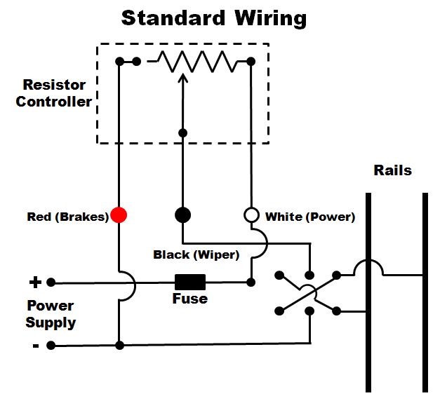
So what I need is a way to wire the power from the Trackmate power supply I have, through the double pole directional switch (6 soldering points), and then to the two jacks (3 soldering points on each) and on out to the track. I have a basic understanding of wiring essentials and soldering wires is no problem, but I need a diagram to make sure I wire it correctly.
Anyone out there who could help?
Thanks,
Keith
Re: Wiring a 2 in 1 controller station
Posted:
Mon Sep 29, 2014 6:49 pmby HomeRacingWorld
I think the 3rd diagram is what you want?

Re: Wiring a 2 in 1 controller station
Posted:
Mon Sep 29, 2014 11:42 pmby Retro Racer 44
That looks really good, Harry, but now my question is how to wire the second controller in as well. Could the switch be on the power supply leads instead of interconnected to the jacks, so that it switches both lanes direction at the same time. Sort of like reversing the leads on the power pack but with a switch?
Keith
Re: Wiring a 2 in 1 controller station
Posted:
Tue Sep 30, 2014 6:31 amby HomeRacingWorld
You would need to wire it as shown, not just at the power. That effects the controllers as well. One extra switch isn't that much extra work and still easy enough to quickly change direction.
Although you might want to wire them away from the drivers panel, as the little ones might learn fast how cool it is to go the other way while racing :)
Re: Wiring a 2 in 1 controller station
Posted:
Tue Sep 30, 2014 11:03 amby Retro Racer 44
Good thought! I think I might just use the jacks and if I want to change direction simply reverse the power leads at the supply box. It might not be very good for cars to be suddenly reversed.
Thanks for your help, especially the diagrams. I think I should be able to do it now.
Cheers,
Keith
Re: Wiring a 2 in 1 controller station
Posted:
Tue Sep 30, 2014 2:51 pmby RichD
If you switch the leads at the power supply to change directions you will also reverse the controller polarity. That will not cause a problem if you stick with resistor controllers, but most electronic controllers will no longer work when you reverse polarity. It is better to have a reversing switch for each lane that is located between the controller and the track.
Re: Wiring a 2 in 1 controller station
Posted:
Sun Oct 05, 2014 11:03 pmby philo426
I am considering building my own 1/24 track.I am thinking the 4th diagram would work.if I want to wire the other lane ,would it be ok just to duplicate the first and connect the other controller wires to the other one or would it need its own separate transformer?
Re: Wiring a 2 in 1 controller station
Posted:
Tue Oct 07, 2014 8:34 amby RichD
If you have large enough power supply and it is regulated you can run all of the lanes from the same supply. You did not say what sort of 1/24ths cars you intended to run. Cars made for commercial raceways use a lot more power than home set cars like Carrera. If the power supply is too small and is not regulated you will get power surges if you use a single power supply. With home set cars you might get by with one amp per lane, but most people power up a four lane track with a 10-20 amp supply. For commercial raceway motors like 16Ds or S16Ds you would need a lot more power, maybe 5 amps per lane. My 20 amp Pyramid power supply screams at me when a S16S motor starts up.