Am in the process of a 2nd 1/32 MDF track in my home.
Wondering if anyone runs a dead stip on their tracks and what timing system you use. Is it possible to run a dead stip while using copper tape ?
Many thanks !
Dead strip timing system questions
11 posts
• Page 1 of 1
Dead strip timing system questions
![]() by bobbyraz49 » Thu Feb 08, 2018 5:16 pm
by bobbyraz49 » Thu Feb 08, 2018 5:16 pm
- bobbyraz49
- HRW SlotCar Veteran!
- Posts: 726
- Joined: Wed Mar 05, 2014 6:08 pm
Re: Dead strip timing system questions
![]() by Pappy » Thu Feb 08, 2018 7:11 pm
by Pappy » Thu Feb 08, 2018 7:11 pm
I have a LapMaster lap counter on my wood track that uses dead strips. I love it.
No reason why you shouldn't be able to use copper tape. I staggered my braid on my dead strips where the guide flap couldn't pick up current from both sides of the track braid and send it into the dead strips at the same time as it passed over them (if that makes any sense).
You can download the LapMaster program on to your computer and play with it but you have to purchase the hardware to make it work on your track.
http://www.lapmaster.dk/
- Pappy
- HRW SlotCar Veteran!
- Posts: 587
- Joined: Mon Jul 20, 2015 9:37 pm
- Location: Oxford, Ohio USA
Re: Dead strip timing system questions
![]() by HomeRacingWorld » Thu Feb 08, 2018 7:28 pm
by HomeRacingWorld » Thu Feb 08, 2018 7:28 pm
Sure. I know a couple tracks I race on with tape and dead strip.
-

HomeRacingWorld - HRW Janitor
- Posts: 15569
- Joined: Wed Aug 08, 2012 2:05 pm
- Location: HRW Skunkworks
Re: Dead strip timing system questions
![]() by RichD » Fri Feb 09, 2018 8:00 am
by RichD » Fri Feb 09, 2018 8:00 am
Several of the Shoreline Model Raceways tracks have copper tape with dead strips. If you want to use dead strips several precautions must be taken if you want to connect them directly to a computer. That would not be an option if you were using a computer that only had USB ports because you can't connect directly to those. If you only have USB ports you would have to use a Trackmate interface board or something like an Arduino Uno board. No matter what sort of connection you are using dead strips only work properly in one direction. The issues with dead strips are discussed in this article https://drive.google.com/open?id=0BzLR4 ... GJkSTVEMkE
-

RichD - HRW SlotCar Veteran!
- Posts: 1885
- Joined: Thu Sep 06, 2012 7:41 am
- Location: East Haven, CT
Re: Dead strip timing system questions
![]() by HomeRacingWorld » Fri Feb 09, 2018 8:15 am
by HomeRacingWorld » Fri Feb 09, 2018 8:15 am
-
HomeRacingWorld - HRW Janitor
- Posts: 15569
- Joined: Wed Aug 08, 2012 2:05 pm
- Location: HRW Skunkworks
Re: Dead strip timing system questions
![]() by Rleog » Fri Feb 09, 2018 9:32 am
by Rleog » Fri Feb 09, 2018 9:32 am
I have a routed wood track and definitely wanted dead strips and Race Coordinator software. I'm using the TrackMate dead strip module shown via Harry's link above, connected to a USB port. Setup and connections were straight forward. The module is a bit of an extra expense but, in my experience, worth it.
I love it.
I love it.
- Rleog
- HRW SlotCar Veteran!
- Posts: 562
- Joined: Mon Dec 17, 2012 6:43 am
- Location: Middleton, MA
Re: Dead strip timing system questions
![]() by bobbyraz49 » Mon Feb 12, 2018 7:39 am
by bobbyraz49 » Mon Feb 12, 2018 7:39 am
I am probably going with the Trackmate system because it is used at a couple local tracks.
Can one (or more) of you fine people take a picture of the wiring of a dead strip from under your track ? Thanks !
Can one (or more) of you fine people take a picture of the wiring of a dead strip from under your track ? Thanks !
- bobbyraz49
- HRW SlotCar Veteran!
- Posts: 726
- Joined: Wed Mar 05, 2014 6:08 pm
Re: Dead strip timing system questions
![]() by Rleog » Mon Feb 12, 2018 9:34 am
by Rleog » Mon Feb 12, 2018 9:34 am
Not sure how to get the links changed so that the photos show here but I'll work on it.
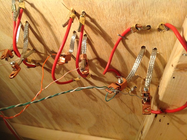
In the second pic, the larger gauge red insulated wires connect track braid from before and after the dead strips, providing track circuit continuity.
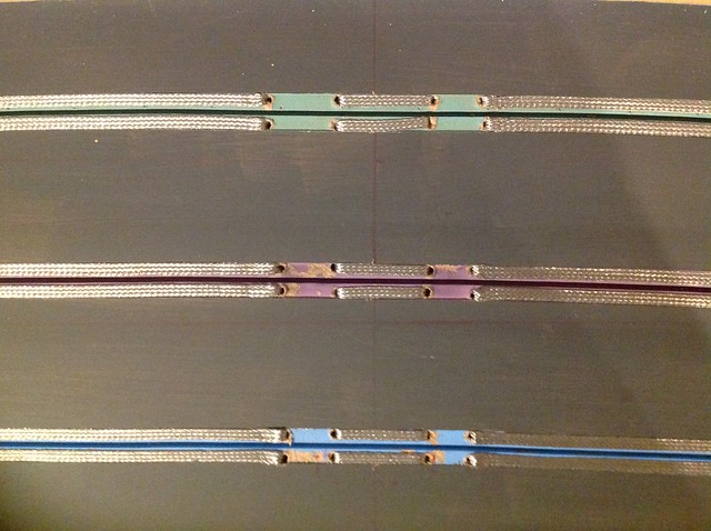
Three lanes; two dead strips, + and -, to each lane. The cut ends of each dead strip are joined by a copper electrical connector and a thin color coded wire from the TrackMate module is connected to each dead strip. Example: the green solid colored wire is connected to the positive braid of a lane while the green and white striped wire is connected to the negative braid of that lane. The TrackMate module supports four lanes.
Electrical tape (or a whole different set of connectors, lol) can be used to wrap and isolate the connections to prevent shorts across the + and - braid connections.
Many installations are much 'cleaner', but hopefully you'll get an idea of what's involved.
- Rleog
- HRW SlotCar Veteran!
- Posts: 562
- Joined: Mon Dec 17, 2012 6:43 am
- Location: Middleton, MA


Re: Dead strip timing system questions
![]() by Rleog » Tue Feb 13, 2018 4:30 pm
by Rleog » Tue Feb 13, 2018 4:30 pm
Ya....what he said!
:text-goodpost:
:text-goodpost:
- Rleog
- HRW SlotCar Veteran!
- Posts: 562
- Joined: Mon Dec 17, 2012 6:43 am
- Location: Middleton, MA
11 posts
• Page 1 of 1
Who is online
Users browsing this forum: No registered users and 19 guests

Powered by phpBB® Forum Software © phpBB Group