by Cjent:
Any time you scarify, scrape, scratch and gouge metal with sand paper and wire wheels, you are setting it up for exposure to the elements that cause corrosion, oxidation, rust, tarnish, etc. You also create crevasses in the metal surface that collect moisture, oil, dust, dirt, and debris. Another thing to consider is that the very thin protective plating applied at the factory on the rail surface is stripped off exposing the bare base metal. For these reasons, I choose not to clean track rails or any metal surfaces with harsh abrasives. I find micro-polishing with a fingernail buffing block to be a better solution to metals cleanup. Yes, even when you polish metal, you are still removing some of the surface but in a less harmful way by creating only microscopic grooves in the surface. The smaller the grooves, the less likely to collect any undesirable substances.
Chemical cleaners such as Windex clean the track well. 409 is also popular as it degreases the surface. Rail Zip and Deoxit, or any anti oxidizing protectors work well also. As I said before, WD-40 protects but leaves an oily residue. However…..
None of the above methods condition and protect the rails with a CONDUCTIVE coating. Only Aero-Car’s Slot Rail & Braid Cleaner/ Conditioner does that.
In summary, new track should not be cleaned with anything abrasive. Why ruin what the factory gave you? Used track can be cleaned and conditioned as I mentioned above. Be good to your track and it will last you a long time.
..................BUILDING TIPS.....................
30 posts
• Page 2 of 2 • 1, 2
Cleaning Your Track - By Sirslotsalot
![]() by LibertyFLHTC » Sun Sep 23, 2012 8:13 am
by LibertyFLHTC » Sun Sep 23, 2012 8:13 am
-

LibertyFLHTC - HRW SlotCar Veteran!
- Posts: 125
- Joined: Tue Sep 04, 2012 6:03 pm
- Location: Iowa, USA
Perfect cutters!!
![]() by LibertyFLHTC » Sun Sep 23, 2012 8:14 am
by LibertyFLHTC » Sun Sep 23, 2012 8:14 am
by Broman62:
Here are a couple pair of cutters that I use for SCX chassis', any plastic pieces and even smaller pieces of wood!! They make perfect straight cuts for when ya need to shorten up or extend a chassis and want to fit it back together!! They are Craftsman from Sears!! The bottom pair are precision nippers for that delicate work!!

Here are a couple pair of cutters that I use for SCX chassis', any plastic pieces and even smaller pieces of wood!! They make perfect straight cuts for when ya need to shorten up or extend a chassis and want to fit it back together!! They are Craftsman from Sears!! The bottom pair are precision nippers for that delicate work!!
-
LibertyFLHTC - HRW SlotCar Veteran!
- Posts: 125
- Joined: Tue Sep 04, 2012 6:03 pm
- Location: Iowa, USA
The Gripper!!
![]() by LibertyFLHTC » Sun Sep 23, 2012 8:15 am
by LibertyFLHTC » Sun Sep 23, 2012 8:15 am
by Broman62:
Another great item I found that has come in handy more times then I can say when workin' in the slotcave!! Its one of those tacky/grippy type jar lid openers!!!! I cut it into smaller pieces and use it to hold onto anything that ya need to grip such as a wheel on an SCX/Carrera, axles if your cuttin' them on your dremel or just about anything that is slickery!!! A have need in the slotcave!!!

Another great item I found that has come in handy more times then I can say when workin' in the slotcave!! Its one of those tacky/grippy type jar lid openers!!!! I cut it into smaller pieces and use it to hold onto anything that ya need to grip such as a wheel on an SCX/Carrera, axles if your cuttin' them on your dremel or just about anything that is slickery!!! A have need in the slotcave!!!
-
LibertyFLHTC - HRW SlotCar Veteran!
- Posts: 125
- Joined: Tue Sep 04, 2012 6:03 pm
- Location: Iowa, USA
Re: ..................BUILDING TIPS.....................
![]() by LibertyFLHTC » Sun Sep 23, 2012 8:17 am
by LibertyFLHTC » Sun Sep 23, 2012 8:17 am
by gonegonzo:
Tom ,
You can also use that material for cosmetic painting. If you paint a chassis or body panel silver , lay the perferated material over it and then spray it flat balck , it takes on the "carbon fiber " look .
Gonzo
Tom ,
You can also use that material for cosmetic painting. If you paint a chassis or body panel silver , lay the perferated material over it and then spray it flat balck , it takes on the "carbon fiber " look .
Gonzo
-
LibertyFLHTC - HRW SlotCar Veteran!
- Posts: 125
- Joined: Tue Sep 04, 2012 6:03 pm
- Location: Iowa, USA
Re: ..................BUILDING TIPS.....................
![]() by LibertyFLHTC » Sun Sep 23, 2012 8:17 am
by LibertyFLHTC » Sun Sep 23, 2012 8:17 am
by Barfly101:
If you are using a ink jet printer for some of your scenery,
try giving your prints two or three of lite coats of hair spray as a sealer.
Sealing the ink like this will help keep the ink from running when applying
thick coatings like triple think, mod podge, polyurethane etc...
Joe.
If you are using a ink jet printer for some of your scenery,
try giving your prints two or three of lite coats of hair spray as a sealer.
Sealing the ink like this will help keep the ink from running when applying
thick coatings like triple think, mod podge, polyurethane etc...
Joe.
-
LibertyFLHTC - HRW SlotCar Veteran!
- Posts: 125
- Joined: Tue Sep 04, 2012 6:03 pm
- Location: Iowa, USA
Re: ....BUILDING TIP-Connecting SCX to Carrera Track
![]() by Cjent » Fri Oct 05, 2012 8:11 am
by Cjent » Fri Oct 05, 2012 8:11 am
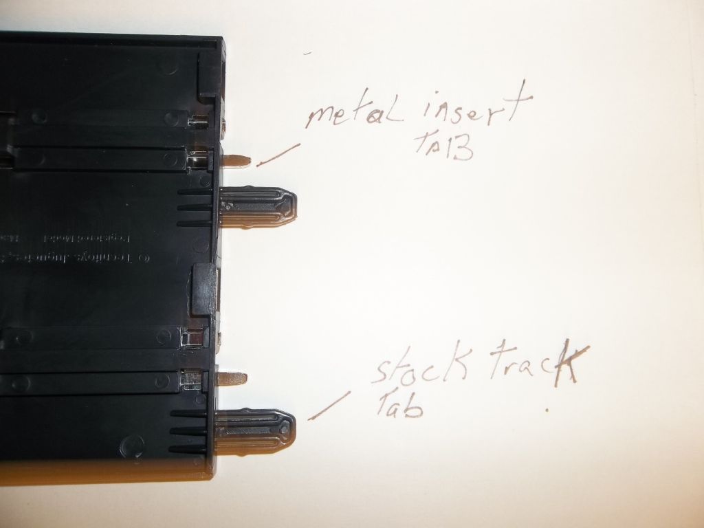
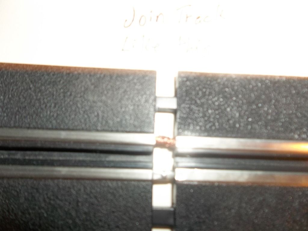
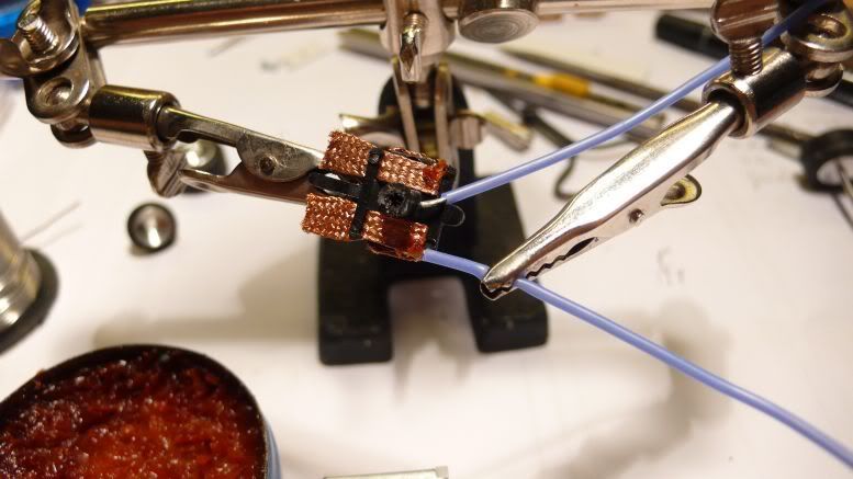
Here's what I did to connect SCX Compact and Carrera GO!!! together. (racer6583 Tip)
It is best if you remove the power rail first as there is a piece of plastic under the metal tab on the rail that needs to be removed for this to work on the SCX piece of track
http://i1189.photobucket.com/albums/z43 ... 2_0954.jpg
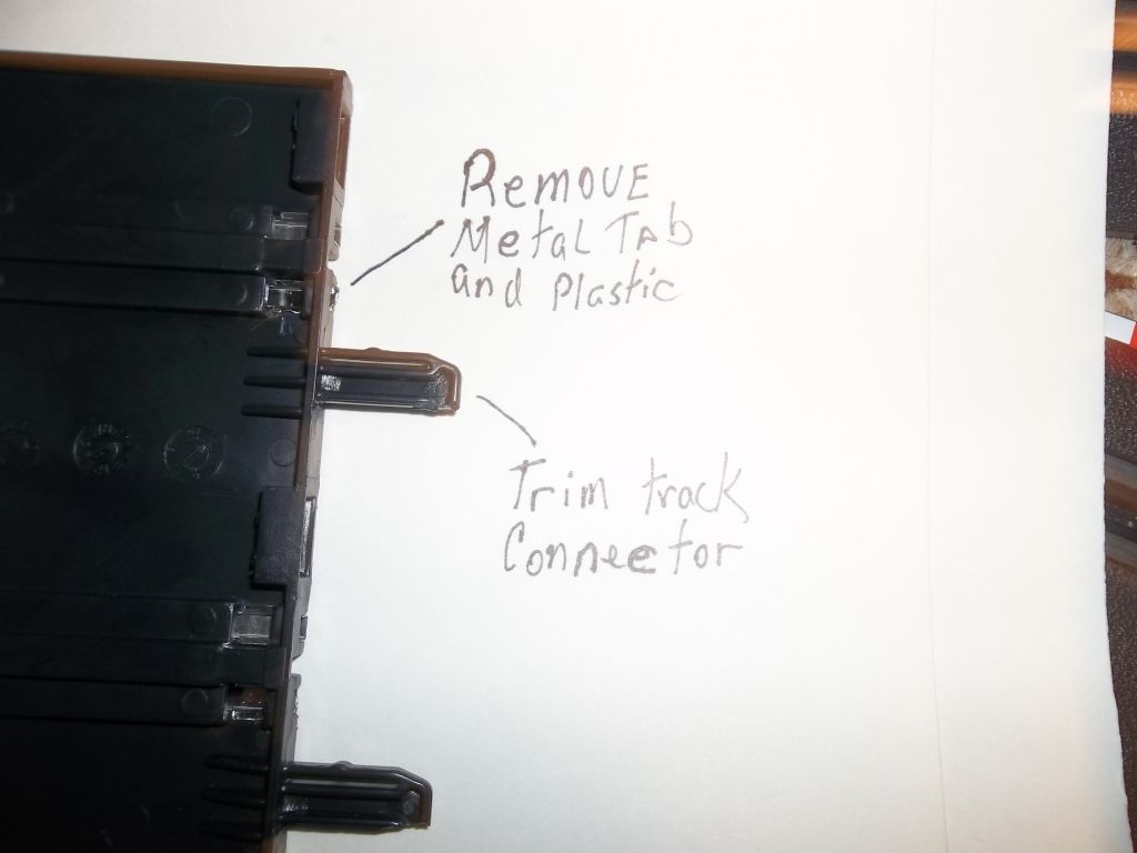
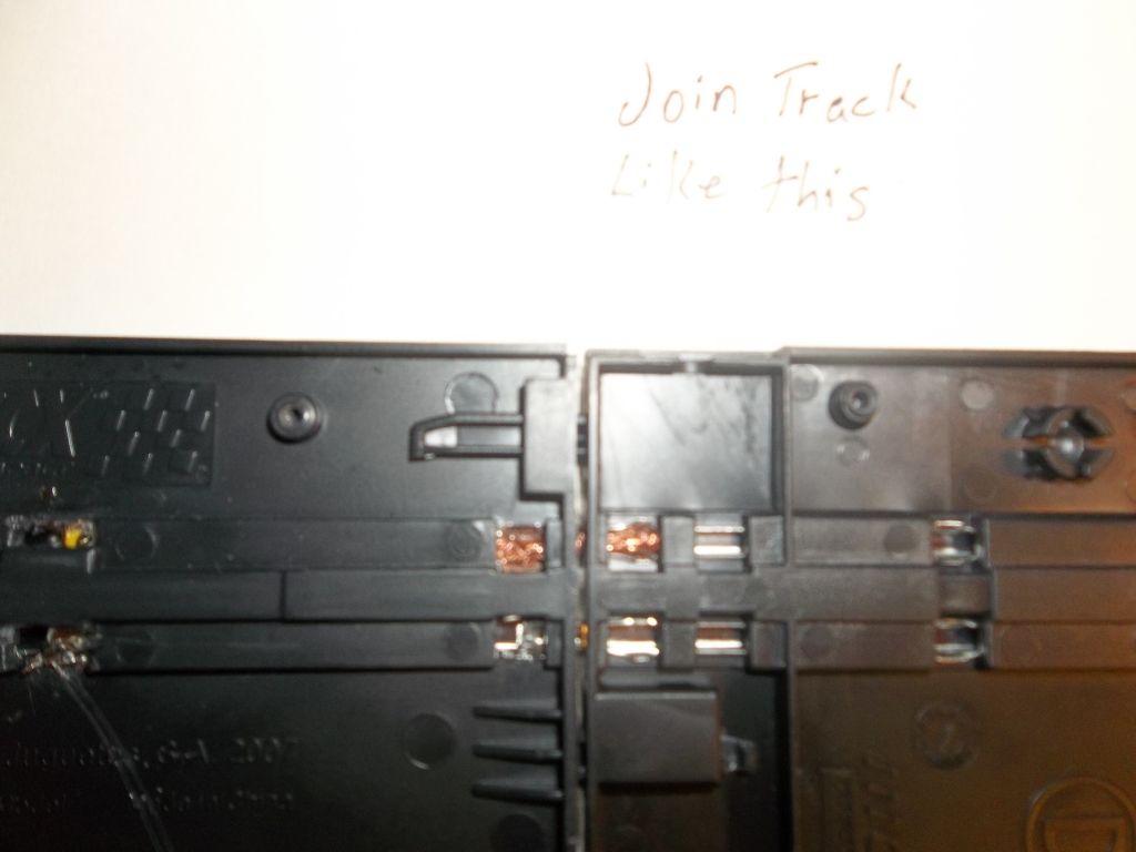
After trimming reinstall the power rail
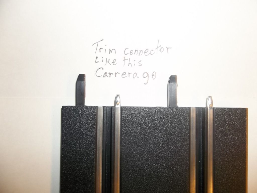
http://i1189.photobucket.com/albums/z43 ... 2_0955.jpg
http://i1189.photobucket.com/albums/z43 ... 2_0957.jpg
http://i1189.photobucket.com/albums/z43 ... 2_0958.jpg
http://i1189.photobucket.com/albums/z43 ... 2_0960.jpg
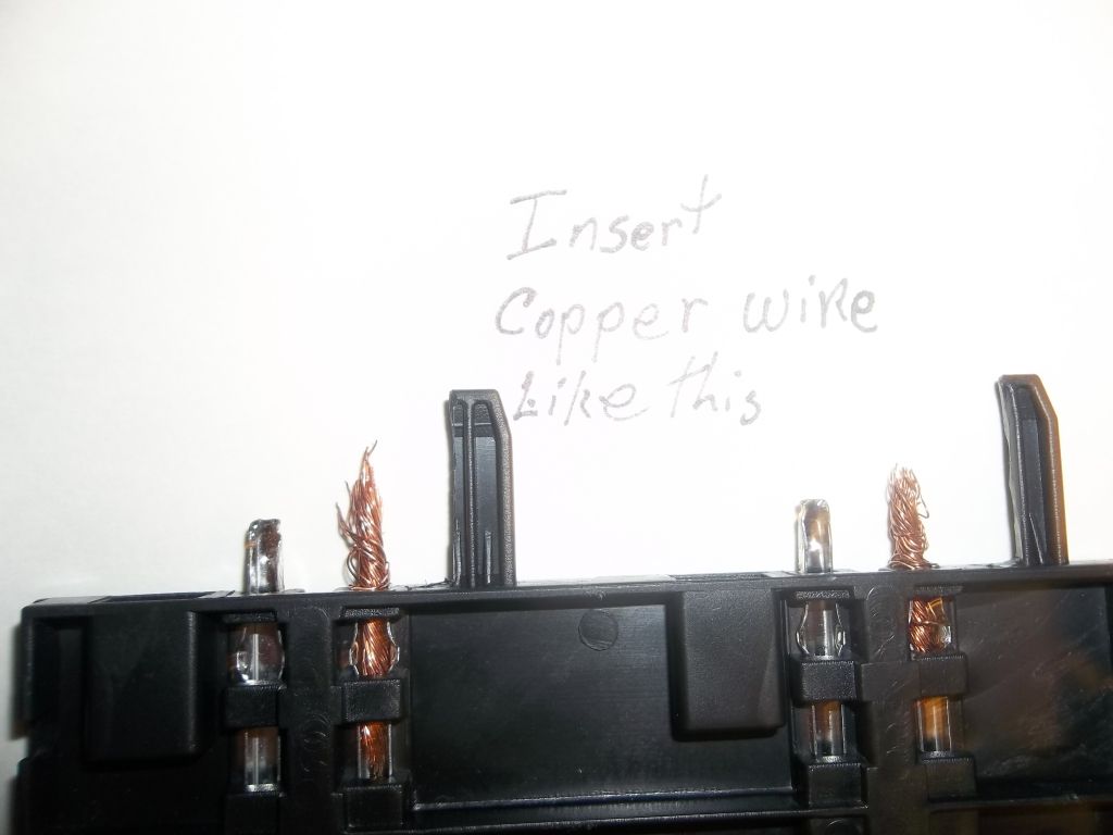
where the copper wire is you could put solder there instead of the wire,but my set up is temp and I left it that way so I can take and put the track away when done goofing around with my ideas that I have.
http://i1189.photobucket.com/albums/z43 ... 2_0959.jpg
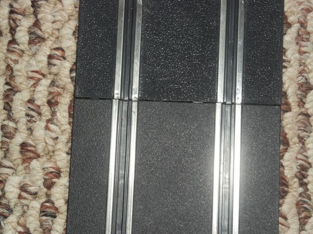
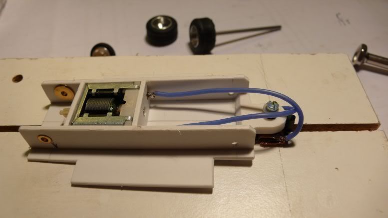
when you put the two tracks together make sure the cars can go a cross smoothly by pushing the car slowly to see if the power rail catches the bottom of the car.
http://i1189.photobucket.com/albums/z43 ... 2_0932.jpg
If the car catches the rail take a small flat tip screwdriver and press the rail down to let the car pass over the joint without the joint catching the car and that's it.
Rex
It is best if you remove the power rail first as there is a piece of plastic under the metal tab on the rail that needs to be removed for this to work on the SCX piece of track
http://i1189.photobucket.com/albums/z43 ... 2_0954.jpg
After trimming reinstall the power rail
http://i1189.photobucket.com/albums/z43 ... 2_0955.jpg
http://i1189.photobucket.com/albums/z43 ... 2_0957.jpg
http://i1189.photobucket.com/albums/z43 ... 2_0958.jpg
http://i1189.photobucket.com/albums/z43 ... 2_0960.jpg
where the copper wire is you could put solder there instead of the wire,but my set up is temp and I left it that way so I can take and put the track away when done goofing around with my ideas that I have.
http://i1189.photobucket.com/albums/z43 ... 2_0959.jpg
when you put the two tracks together make sure the cars can go a cross smoothly by pushing the car slowly to see if the power rail catches the bottom of the car.
http://i1189.photobucket.com/albums/z43 ... 2_0932.jpg
If the car catches the rail take a small flat tip screwdriver and press the rail down to let the car pass over the joint without the joint catching the car and that's it.
Rex
-

Cjent - HRW SlotCar Veteran!
- Posts: 1218
- Joined: Thu Aug 30, 2012 3:39 pm
- Location: FL & AL
Re: ..................BUILDING TIPS.....................
![]() by LloydL » Tue Oct 09, 2012 9:08 am
by LloydL » Tue Oct 09, 2012 9:08 am
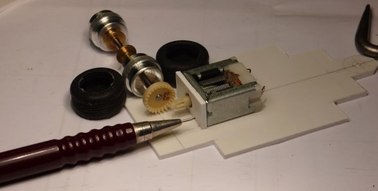
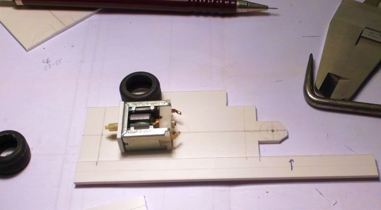
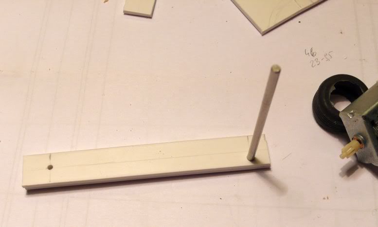
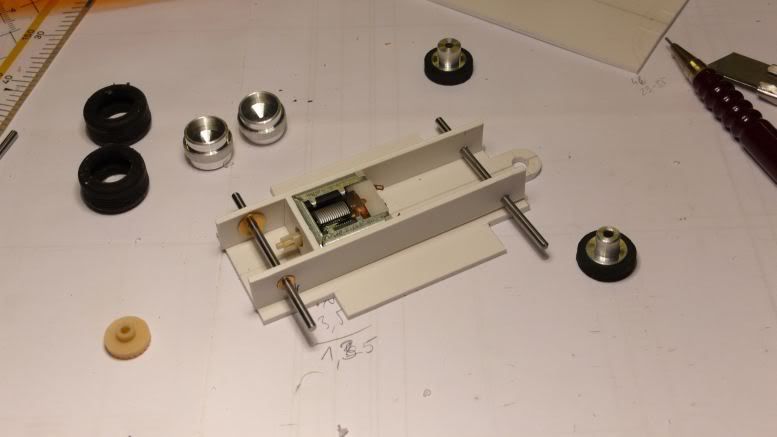
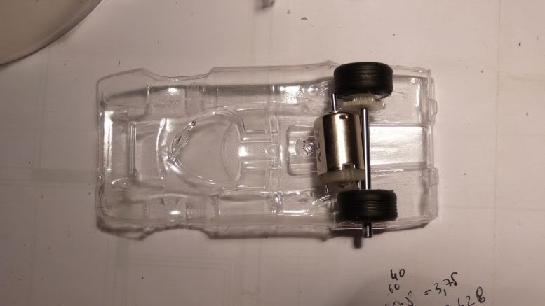
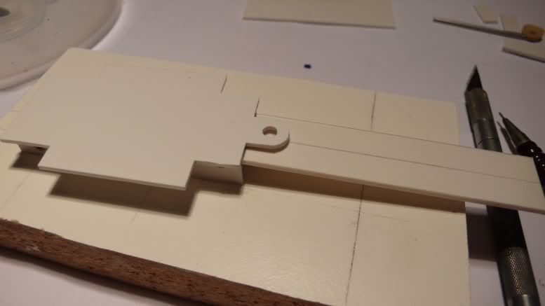
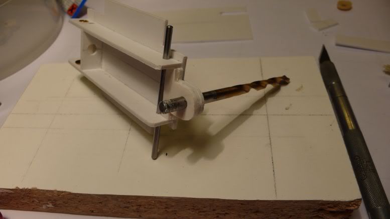
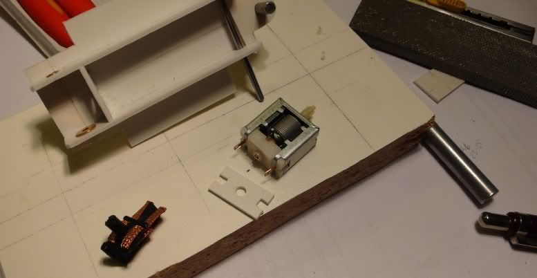
FRONT AXLE MOUNTS.
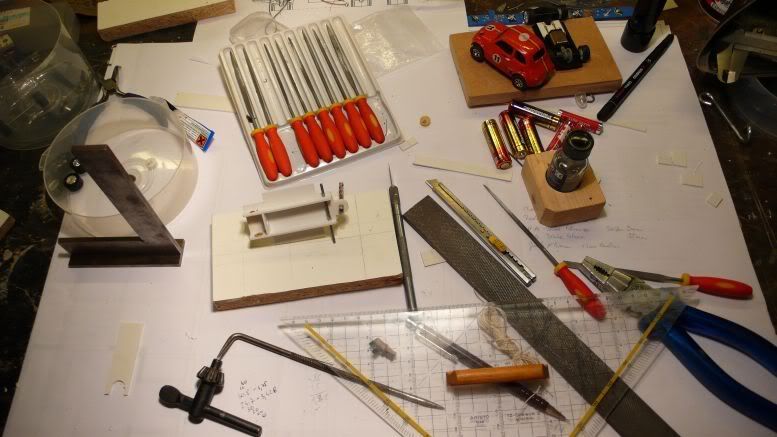
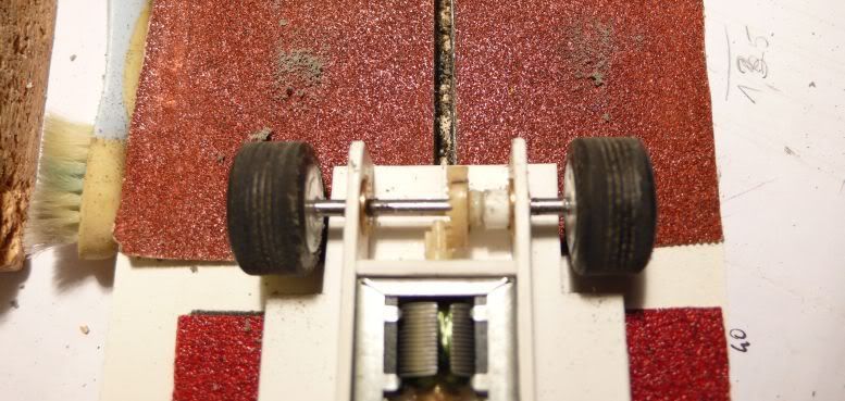
I have been asked about the front axle mounts on my Pronomag Lola T70 chassis. I like to build from whatever I have around and thought that these parts looked useful.
The photos should show how it was done. Please ask if they dont!


Regards, Lloyd
I have been asked about the front axle mounts on my Pronomag Lola T70 chassis. I like to build from whatever I have around and thought that these parts looked useful.
The photos should show how it was done. Please ask if they dont!
Regards, Lloyd
-

LloydL - HRW SlotCar Veteran!
- Posts: 802
- Joined: Thu Sep 06, 2012 5:48 am
- Location: Norwich, UK
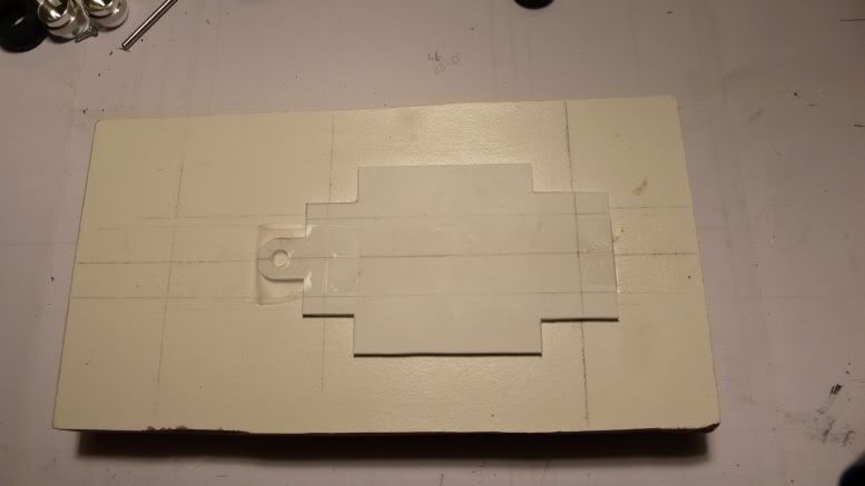
scratch build styrene chassis
![]() by LibertyFLHTC » Tue Oct 16, 2012 4:14 am
by LibertyFLHTC » Tue Oct 16, 2012 4:14 am
By Peter:
with the big scratchbuild proxy comming nearer and nearer, i wanted to start with an entry. Decision was a homemade body, MCE Centenaire, vac-formed from a Bburago diecast with a styrene chassis.
for a start, i took the measurements on the body - width, wheelbase
what will be the distance from the guide flag hole to the front axle?
next step - aplly all data to the PS sheet, also the size of the wheels, to cut openings big enough for the wheels, plus a little space. i want the base plate of the chassis as wide as the body is.
cutting the PS sheet with a cutter is quite easy. the thickness of my PS is 1.5mm.
all parts are on the table.
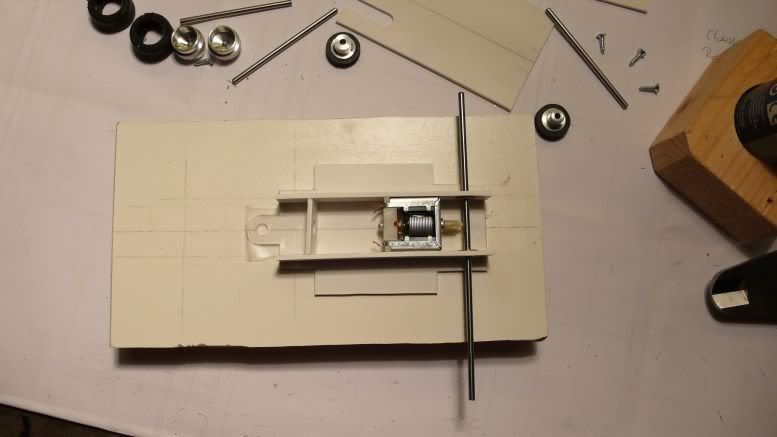
measuring the distance from the rear axle to the rear cross brace
marking the wheel base and the length on the longitudinal braces, right away from the base plate.
the height of the rear axle depends on the height of the motor. measuring the height of the motor, half of it is the height of the center line of the rear axle.
i drill one longitudinal brace first, than lay it over the 2nd and drill them together. first the front axle hole, put an axle in, then the rear axle hole. in this way both will have the same wheel base. note the front axle hole is lower, as my front wheels have 13mm diameter and the rears have 17mm. so the front axle hole has to be lower by 2mm.
put the ranch-design bearings into the PS and pre-assembled:
next step: glueing the longitudinal and cross braces to the base plate.
more pics to come.
puddle dude
Part 2
here is the next step: i glued the base plate with scotch tape to my setup block, to see if the rear axle is perpendicular to middle line - needed for good traction:
ranchdesign bearings glued into the side braces before glueing the side braces to the base plate, then revell glue to the side and ACTION.
now i´ll let the glue settle until tomorrow evening (learned that part!) to allow real hardening
Mas, in the end i let my eyes do the last check, too. but during the first phases, i measure a lot. saves some time afterwards (maybe). And the rear wheels are stock artin replacement wheels from ranch-design. K&D racing tires are my choice for the tires.
Chuck, yes i like the body. the wheel base is right on the long artin plus it is WIDE. enough place to work inside. plus it looks cool (for me).
Marioyee, you´re welcome. glad to help.
Tom, i cut the styrene with a cutter or even with an old jigsaw (you know like the ones you get a kid to cut thin plywood, that´s the one i still use). let´s see what you use!
Part 3
the guide (from RD) had the top cut off to fit under the hood. It has to go higher, so i´ll cut the inner front piece out and glue another piece over the existing. in this way, the guide will sit high enough in the chassis to allow the front wheels to touch the track slightly. Also found a little warp in the ready glued chassis. I´ll fix this as i put the chassis in hot water and than twist it slightly in the opposite way of the warp and let it cool down (this process can be fastened by putting the chassis under cold water ).
I´ll be satisfied when all 4 wheels touch the track at once without wobbling when pushing down at one corner.
now also look to get the body easy over the chassis, the side will be shaped along the body lines.
i think for this motor/gear combination i´ll also have to build a chassis by myself. seems to fit nicely inside the body i´ve choosen. a bonus banana for the first who guesses the body right
puddle dude
Part 4
marking the extension parts for the guide as it needs to go higher in the chassis
parts cutted and glued to the chassis, the will be filed down after the glue has hardened.
cutting the 2nd motor mount, holes for the wires filed out
work bench is in the normal mess again
Part 4
Ed, thanks, i´m using modell glue from Revell for glueing the styrene. Applied with the brush that comes with the glue (inside the top cover of the bottle)
and Mas is the winner of the banana - here it is image
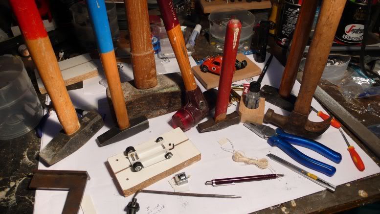
Steve, are these enough hammers?
normally i start using the hammers after the build is ready, for setup issues
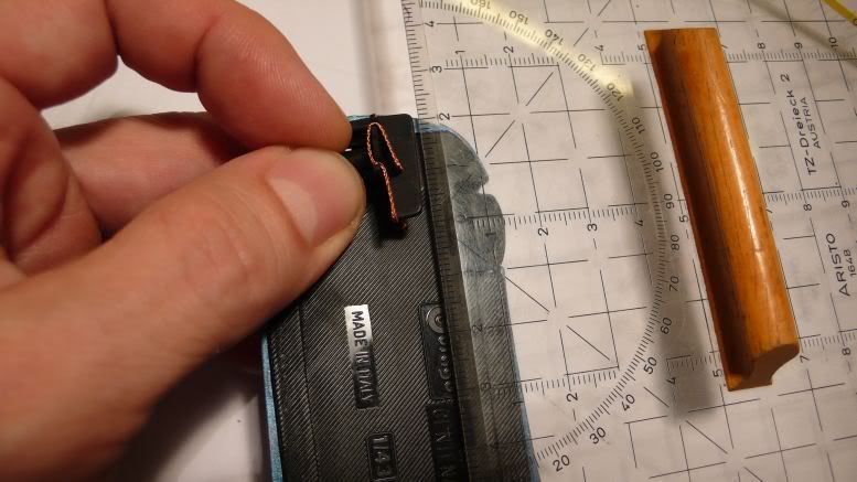
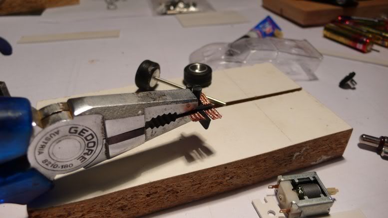
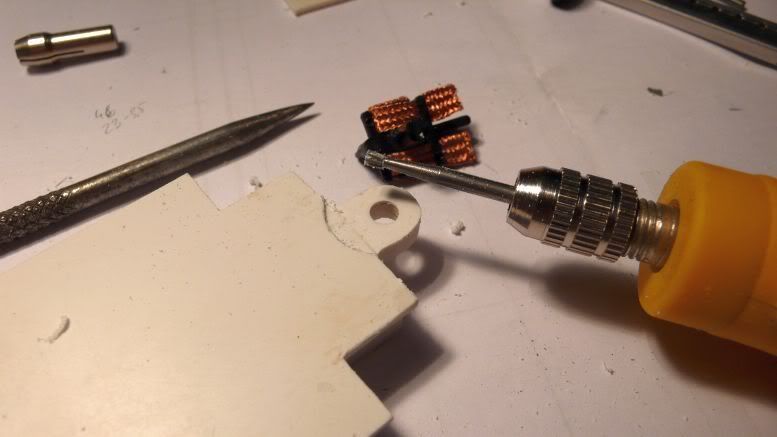
setting up the braid, the top right braid is stock, the other are in form already. to get the top side of the braid nicely flat to enable easy rotation of the guide:
shaping the underside of the chassis to allow the guide to get a little deeper into the chassis. the part of the guide holder outside the longitudinal braces was filed down, for the circular part the dremel was used.
controll of the works: the front wheels should go up a little in the chassis, this clarifys Steve´s question if i can use all the measurement gears - NO even that or i can´t calculate
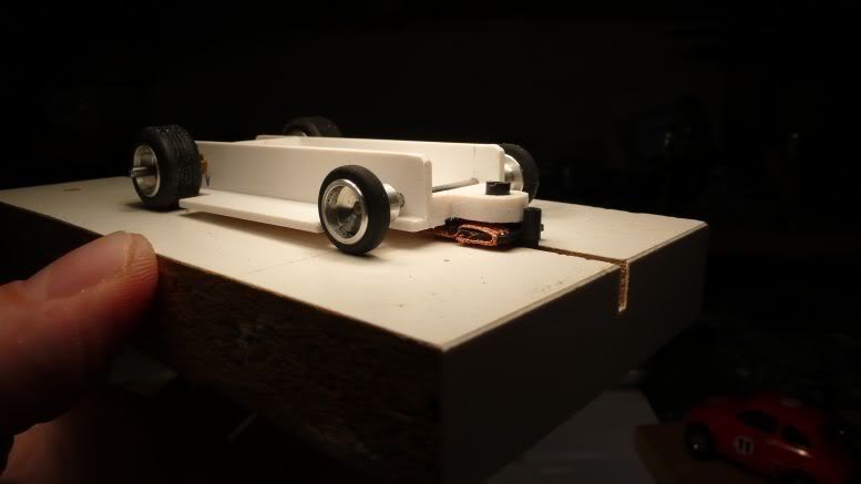
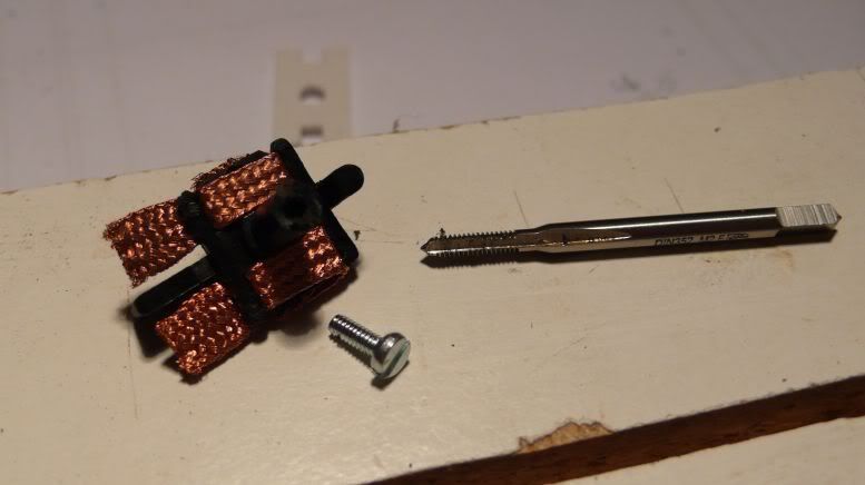
drilling a hole inside the guide to be able to fasten the guide in the chassis:
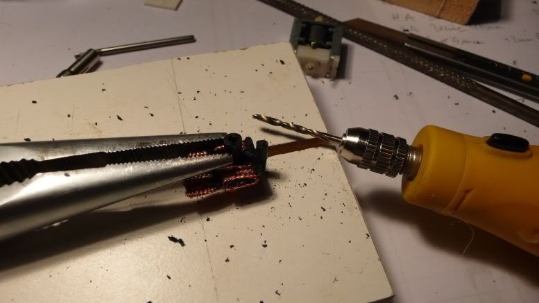
using a thread cutter M2, cut thread by hand worked great. now there is something for the screw to grub into
Part 5
the rear wheel wells will have to be widen a little, using the sanding drum in the dremel will do this job:
soldering the high flexible guide wire to the RD guide, i use some extra flux (as can be seen in the lower left corner of the pic) to get an easy soldering point. soldering the wire to the outside of the braid will allow an easy rotation of the guide.
soldered the wire to the motor as well and glued the motor cross brace into the chassis. the 2nd brace holds the motor, so no glue on the motor and only on the side of the cross brace, to allow an easier removement if that should be necessary.
checking the axle lenght, i mount one wheel, mark the other side and then cut the axle with the hand steel saw. rounding of the edges of the axle with a fine file.
Notice also the styrene pipe parts - spacer to get the right width of the front axle.
filing down the last amount of axle
the crown spacer pipe is glued to the chassis and trimmed with a fine file to the right length.
i glued the wires to the sides of the chassis so they stay in place and still have enough movement, just near the front axle.
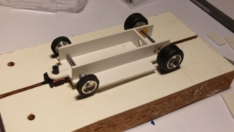
Part 6
next step on the personal todo list: glueing the tires to the rims. always a hairy thing to do ruined some tires in this way, but in 19 out of the 20 cases it works great.
apply CA inside the tire and put it over the rim.
putting the axle into the chassis, push the crown to the crown post, not the other way
2nd wheel is glued to the axle, putting small drops of CA under the tire under the parts where the glue did not go in the first step. sometimes i think if it would be better the glue the whole tire in this way to the rim?
before i start with tire sanding
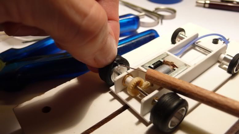
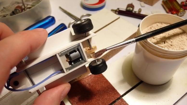
, i aplly pumice powder (with a little water) to the pinion/crown to help breaking it in. could also be done with toothpaste. i use the pumice powder also with a toothbrush to clean/sand resin bodies.
slightly oil the axle
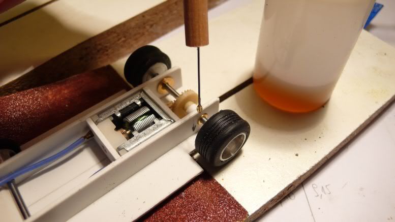
start sanding - always watch the motor temperature and the tire temperature while tire sanding
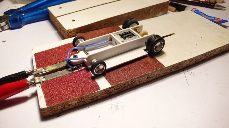
after the first sanding, the tire are getting quite good contact now ...
Part 7
i hate it really when the CA glue is empty when i want to finish something.
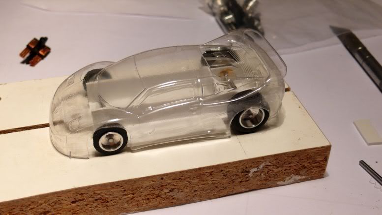
Anyway, i glued short brass posts to the sides of the chassis for body mounting.
marking the positions where the holes in the body should go.
i found out that the easiest way to get the first holes into a vac-formed body is with the tip of the soldering iron. After the first holes i widen the holes with a reames of the correct size of the brass posts.
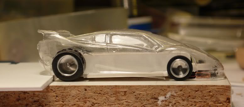
the body is mounted
END of the story
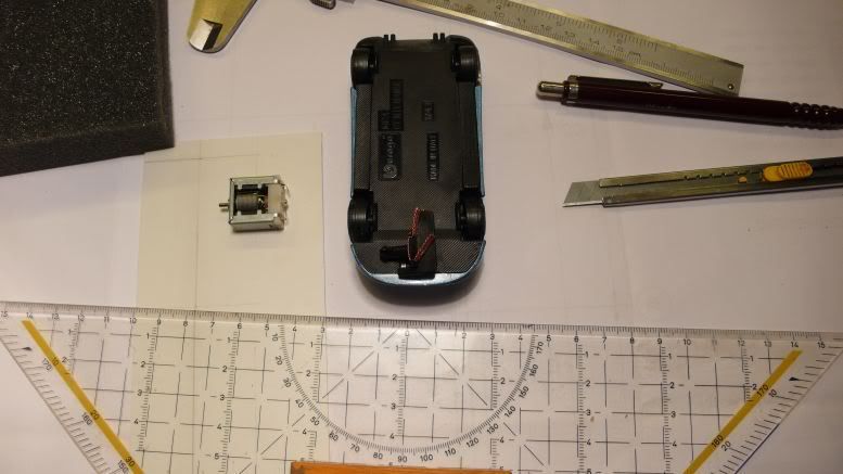
with the big scratchbuild proxy comming nearer and nearer, i wanted to start with an entry. Decision was a homemade body, MCE Centenaire, vac-formed from a Bburago diecast with a styrene chassis.
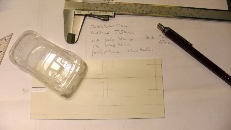
for a start, i took the measurements on the body - width, wheelbase
what will be the distance from the guide flag hole to the front axle?
next step - aplly all data to the PS sheet, also the size of the wheels, to cut openings big enough for the wheels, plus a little space. i want the base plate of the chassis as wide as the body is.
cutting the PS sheet with a cutter is quite easy. the thickness of my PS is 1.5mm.
all parts are on the table.
measuring the distance from the rear axle to the rear cross brace
marking the wheel base and the length on the longitudinal braces, right away from the base plate.
the height of the rear axle depends on the height of the motor. measuring the height of the motor, half of it is the height of the center line of the rear axle.
i drill one longitudinal brace first, than lay it over the 2nd and drill them together. first the front axle hole, put an axle in, then the rear axle hole. in this way both will have the same wheel base. note the front axle hole is lower, as my front wheels have 13mm diameter and the rears have 17mm. so the front axle hole has to be lower by 2mm.
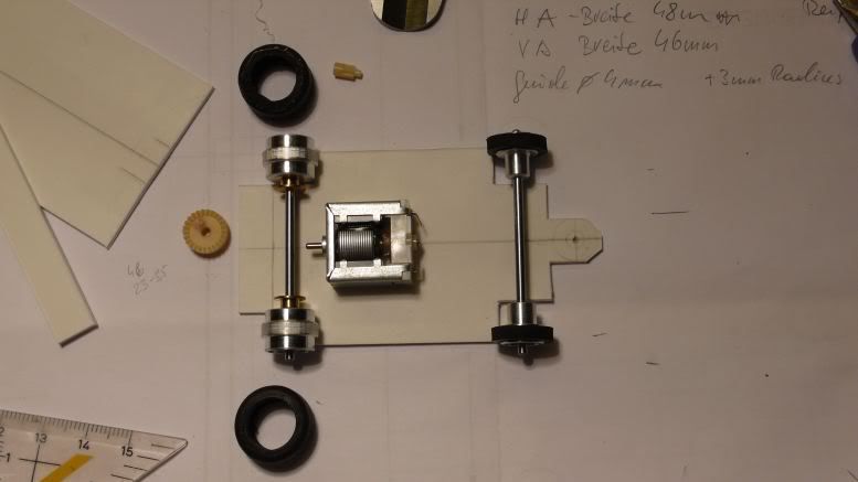
put the ranch-design bearings into the PS and pre-assembled:
next step: glueing the longitudinal and cross braces to the base plate.
more pics to come.
puddle dude
Part 2
here is the next step: i glued the base plate with scotch tape to my setup block, to see if the rear axle is perpendicular to middle line - needed for good traction:
ranchdesign bearings glued into the side braces before glueing the side braces to the base plate, then revell glue to the side and ACTION.
now i´ll let the glue settle until tomorrow evening (learned that part!) to allow real hardening
Mas, in the end i let my eyes do the last check, too. but during the first phases, i measure a lot. saves some time afterwards (maybe). And the rear wheels are stock artin replacement wheels from ranch-design. K&D racing tires are my choice for the tires.
Chuck, yes i like the body. the wheel base is right on the long artin plus it is WIDE. enough place to work inside. plus it looks cool (for me).
Marioyee, you´re welcome. glad to help.
Tom, i cut the styrene with a cutter or even with an old jigsaw (you know like the ones you get a kid to cut thin plywood, that´s the one i still use). let´s see what you use!
Part 3
the guide (from RD) had the top cut off to fit under the hood. It has to go higher, so i´ll cut the inner front piece out and glue another piece over the existing. in this way, the guide will sit high enough in the chassis to allow the front wheels to touch the track slightly. Also found a little warp in the ready glued chassis. I´ll fix this as i put the chassis in hot water and than twist it slightly in the opposite way of the warp and let it cool down (this process can be fastened by putting the chassis under cold water ).
I´ll be satisfied when all 4 wheels touch the track at once without wobbling when pushing down at one corner.
now also look to get the body easy over the chassis, the side will be shaped along the body lines.
i think for this motor/gear combination i´ll also have to build a chassis by myself. seems to fit nicely inside the body i´ve choosen. a bonus banana for the first who guesses the body right
puddle dude
Part 4
marking the extension parts for the guide as it needs to go higher in the chassis
parts cutted and glued to the chassis, the will be filed down after the glue has hardened.
cutting the 2nd motor mount, holes for the wires filed out
work bench is in the normal mess again
Part 4
Ed, thanks, i´m using modell glue from Revell for glueing the styrene. Applied with the brush that comes with the glue (inside the top cover of the bottle)
and Mas is the winner of the banana - here it is image
Steve, are these enough hammers?
normally i start using the hammers after the build is ready, for setup issues
setting up the braid, the top right braid is stock, the other are in form already. to get the top side of the braid nicely flat to enable easy rotation of the guide:
shaping the underside of the chassis to allow the guide to get a little deeper into the chassis. the part of the guide holder outside the longitudinal braces was filed down, for the circular part the dremel was used.
controll of the works: the front wheels should go up a little in the chassis, this clarifys Steve´s question if i can use all the measurement gears - NO even that or i can´t calculate
drilling a hole inside the guide to be able to fasten the guide in the chassis:
using a thread cutter M2, cut thread by hand worked great. now there is something for the screw to grub into
Part 5
the rear wheel wells will have to be widen a little, using the sanding drum in the dremel will do this job:
soldering the high flexible guide wire to the RD guide, i use some extra flux (as can be seen in the lower left corner of the pic) to get an easy soldering point. soldering the wire to the outside of the braid will allow an easy rotation of the guide.
soldered the wire to the motor as well and glued the motor cross brace into the chassis. the 2nd brace holds the motor, so no glue on the motor and only on the side of the cross brace, to allow an easier removement if that should be necessary.
checking the axle lenght, i mount one wheel, mark the other side and then cut the axle with the hand steel saw. rounding of the edges of the axle with a fine file.
Notice also the styrene pipe parts - spacer to get the right width of the front axle.
filing down the last amount of axle
the crown spacer pipe is glued to the chassis and trimmed with a fine file to the right length.
i glued the wires to the sides of the chassis so they stay in place and still have enough movement, just near the front axle.
Part 6
next step on the personal todo list: glueing the tires to the rims. always a hairy thing to do ruined some tires in this way, but in 19 out of the 20 cases it works great.
apply CA inside the tire and put it over the rim.
putting the axle into the chassis, push the crown to the crown post, not the other way
2nd wheel is glued to the axle, putting small drops of CA under the tire under the parts where the glue did not go in the first step. sometimes i think if it would be better the glue the whole tire in this way to the rim?
before i start with tire sanding
, i aplly pumice powder (with a little water) to the pinion/crown to help breaking it in. could also be done with toothpaste. i use the pumice powder also with a toothbrush to clean/sand resin bodies.
slightly oil the axle
start sanding - always watch the motor temperature and the tire temperature while tire sanding
after the first sanding, the tire are getting quite good contact now ...
Part 7
i hate it really when the CA glue is empty when i want to finish something.
Anyway, i glued short brass posts to the sides of the chassis for body mounting.
marking the positions where the holes in the body should go.
i found out that the easiest way to get the first holes into a vac-formed body is with the tip of the soldering iron. After the first holes i widen the holes with a reames of the correct size of the brass posts.
the body is mounted
END of the story
-
LibertyFLHTC - HRW SlotCar Veteran!
- Posts: 125
- Joined: Tue Sep 04, 2012 6:03 pm
- Location: Iowa, USA
Putting Brakes on Carrera GO!!! Controllers
![]() by Cjent » Thu Nov 01, 2012 9:01 am
by Cjent » Thu Nov 01, 2012 9:01 am
Re: Carrera Whoa! pics added
Posted by Dodgefarmer » October 31st, 2012, 8:27 pm
Ok, Here's what I've done.
First of all I've been informed that we are going to Edmonton for Xmas. Where a certain pint sized racer intends to hand me parts of my anatomy on a platter as I've never thumb raced before. Not going to happen!
I put this together a couple of weeks ago to practice thumb control. Plus I was bored with the Artin track. I was not overly impressed with the stock Go controller as it was mostly a matter of holding the plunger down and bumping the turbothrust button. I decided to look inside the controller to see if there was something that could be changed to increase controller response. I discovered that the controller is a 3 wire system, with a black, blue and red wire. I ran resistance tests on the soldered ends of the wires in the controllers and the contact strips at the terminal end. The black wire is a direct feed from the + (pos) on the power pack lead. The blue wire was connected to the rear rail of the lane on the track with 35ohms resistance. The red wire ran through a contact switch activated by the turbothrust button and ran to the rear rail on the track with 3 ohms resistance. This is where the light bulb started to get a faint glow (it takes awhile to get to full intensity) :lol: . I buttoned it back up and pulled the bottom off of a power connection track.
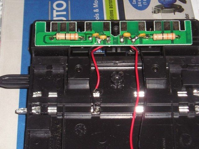
I put this together a couple of weeks ago to practice thumb control. Plus I was bored with the Artin track. I was not overly impressed with the stock Go controller as it was mostly a matter of holding the plunger down and bumping the turbothrust button. I decided to look inside the controller to see if there was something that could be changed to increase controller response. I discovered that the controller is a 3 wire system, with a black, blue and red wire. I ran resistance tests on the soldered ends of the wires in the controllers and the contact strips at the terminal end. The black wire is a direct feed from the + (pos) on the power pack lead. The blue wire was connected to the rear rail of the lane on the track with 35ohms resistance. The red wire ran through a contact switch activated by the turbothrust button and ran to the rear rail on the track with 3 ohms resistance. This is where the light bulb started to get a faint glow (it takes awhile to get to full intensity) :lol: . I buttoned it back up and pulled the bottom off of a power connection track.
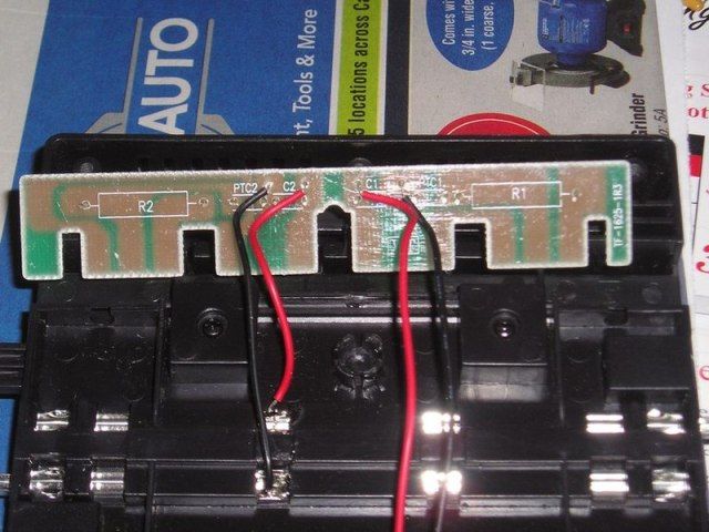
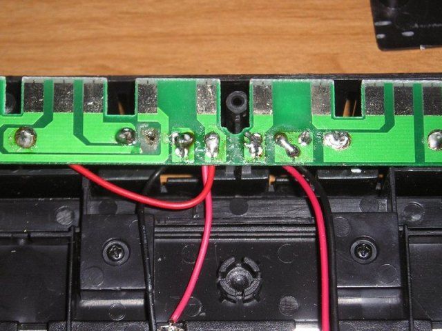
Looking at the circuit board the +(pos) lead from the power supply connection (marked on the track connection terminal) goes direct to the left contact strip on the controller connection. The red wire (turbothrust) from the controller goes to the center contact strip which goes through a 3 ohm resistor to the black wire soldered to the rear rail of the lane The blue wire from the controller goes to the right contact strip through a 33 ohm resistor back to the center contact strip. At this point the light bulb is starting to get real bright.
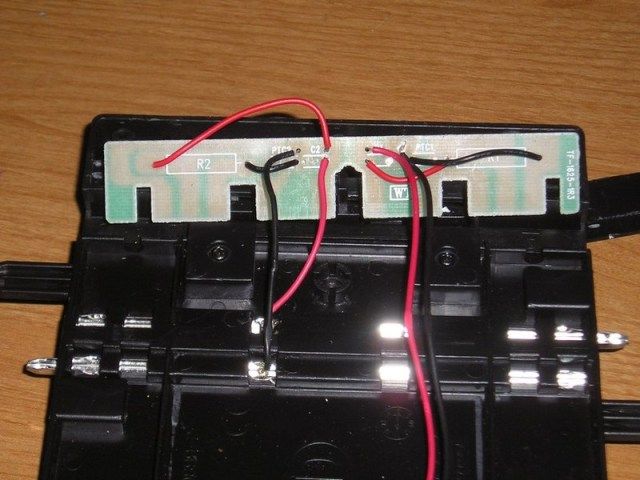
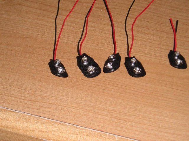
I decided that if I removed all of the resistors and ran a jumper direct from the right hand controller contact to the rear rail contact that I would have full power to the controller. I then decided that if I ran a jumper from center controller contact strip to the front rail contact strip that I could use the turbothrust button as a brake. Here's where reality sets in. I went to The Source (used to be Radio Shack) to get 22 gauge wire in black and red. $11.00 a roll for solid and they only had 1 color. Then I spotted these for $4.95
I made my mods put the bottom plate back on and did a test drive for about 2 hrs. What a difference. I have full control from idle to WOT, instant response from any speed, and the car comes to a complete stop in under 12". Total time was about an hour mostly taken up with pulling the resistors and trying not to touch the circuit board.
Randy
Posted by Dodgefarmer » October 31st, 2012, 8:27 pm
Ok, Here's what I've done.
First of all I've been informed that we are going to Edmonton for Xmas. Where a certain pint sized racer intends to hand me parts of my anatomy on a platter as I've never thumb raced before. Not going to happen!
I put this together a couple of weeks ago to practice thumb control. Plus I was bored with the Artin track. I was not overly impressed with the stock Go controller as it was mostly a matter of holding the plunger down and bumping the turbothrust button. I decided to look inside the controller to see if there was something that could be changed to increase controller response. I discovered that the controller is a 3 wire system, with a black, blue and red wire. I ran resistance tests on the soldered ends of the wires in the controllers and the contact strips at the terminal end. The black wire is a direct feed from the + (pos) on the power pack lead. The blue wire was connected to the rear rail of the lane on the track with 35ohms resistance. The red wire ran through a contact switch activated by the turbothrust button and ran to the rear rail on the track with 3 ohms resistance. This is where the light bulb started to get a faint glow (it takes awhile to get to full intensity) :lol: . I buttoned it back up and pulled the bottom off of a power connection track.
I put this together a couple of weeks ago to practice thumb control. Plus I was bored with the Artin track. I was not overly impressed with the stock Go controller as it was mostly a matter of holding the plunger down and bumping the turbothrust button. I decided to look inside the controller to see if there was something that could be changed to increase controller response. I discovered that the controller is a 3 wire system, with a black, blue and red wire. I ran resistance tests on the soldered ends of the wires in the controllers and the contact strips at the terminal end. The black wire is a direct feed from the + (pos) on the power pack lead. The blue wire was connected to the rear rail of the lane on the track with 35ohms resistance. The red wire ran through a contact switch activated by the turbothrust button and ran to the rear rail on the track with 3 ohms resistance. This is where the light bulb started to get a faint glow (it takes awhile to get to full intensity) :lol: . I buttoned it back up and pulled the bottom off of a power connection track.
Looking at the circuit board the +(pos) lead from the power supply connection (marked on the track connection terminal) goes direct to the left contact strip on the controller connection. The red wire (turbothrust) from the controller goes to the center contact strip which goes through a 3 ohm resistor to the black wire soldered to the rear rail of the lane The blue wire from the controller goes to the right contact strip through a 33 ohm resistor back to the center contact strip. At this point the light bulb is starting to get real bright.
I decided that if I removed all of the resistors and ran a jumper direct from the right hand controller contact to the rear rail contact that I would have full power to the controller. I then decided that if I ran a jumper from center controller contact strip to the front rail contact strip that I could use the turbothrust button as a brake. Here's where reality sets in. I went to The Source (used to be Radio Shack) to get 22 gauge wire in black and red. $11.00 a roll for solid and they only had 1 color. Then I spotted these for $4.95
I made my mods put the bottom plate back on and did a test drive for about 2 hrs. What a difference. I have full control from idle to WOT, instant response from any speed, and the car comes to a complete stop in under 12". Total time was about an hour mostly taken up with pulling the resistors and trying not to touch the circuit board.
Randy
-
Cjent - HRW SlotCar Veteran!
- Posts: 1218
- Joined: Thu Aug 30, 2012 3:39 pm
- Location: FL & AL
Re: ..................BUILDING TIPS.....................
![]() by nerfbarz » Tue Mar 12, 2013 10:27 am
by nerfbarz » Tue Mar 12, 2013 10:27 am
Cjent,
Unca Sal 'n' da boyz fount dis pitcher, dare, ahow a Moickry Cap-ree sopposte t' luck!
http://www.theroaringseason.com/showthr ... inal-Death
Big Vinnie says check out da secun post, dare
Unca Sal 'n' da boyz fount dis pitcher, dare, ahow a Moickry Cap-ree sopposte t' luck!
http://www.theroaringseason.com/showthr ... inal-Death
Big Vinnie says check out da secun post, dare
- nerfbarz
- HRW SlotCar Veteran!
- Posts: 210
- Joined: Sun Sep 30, 2012 10:32 am
Re: ..................BUILDING TIPS.....................
![]() by Cjent » Tue Mar 12, 2013 4:13 pm
by Cjent » Tue Mar 12, 2013 4:13 pm
Interesting, Tom! :D :clap:
-
Cjent - HRW SlotCar Veteran!
- Posts: 1218
- Joined: Thu Aug 30, 2012 3:39 pm
- Location: FL & AL
Re: ..................BUILDING TIPS.....................
![]() by nerfbarz » Wed Mar 13, 2013 8:22 am
by nerfbarz » Wed Mar 13, 2013 8:22 am
I built a motorized (batts) "water truck" which drags a sponge loaded with model RR track cleaner.
Nerf
Nerf
- nerfbarz
- HRW SlotCar Veteran!
- Posts: 210
- Joined: Sun Sep 30, 2012 10:32 am
Re: ..................BUILDING TIPS.....................
![]() by Cjent » Thu Mar 14, 2013 10:52 am
by Cjent » Thu Mar 14, 2013 10:52 am
-
Cjent - HRW SlotCar Veteran!
- Posts: 1218
- Joined: Thu Aug 30, 2012 3:39 pm
- Location: FL & AL
-
Dodgefarmer - HRW SlotCar Veteran!
- Posts: 818
- Joined: Thu Sep 06, 2012 10:11 am
- Location: Grindrod B.C. Canada
Re: ..................BUILDING TIPS.....................
![]() by Rinkrat99 » Thu Jan 12, 2017 12:42 pm
by Rinkrat99 » Thu Jan 12, 2017 12:42 pm
How do you remove that bottom plate off the power track without damage? The two screws seem to hold controller/power box onto the track but is independant of the plate to the track. The two four holed slots are one thing but pics indicate three screws under the controller/pwr terminals. Thoughts?
- Rinkrat99
- Posts: 45
- Joined: Tue Jan 03, 2017 6:06 pm
30 posts
• Page 2 of 2 • 1, 2
Who is online
Users browsing this forum: No registered users and 3 guests

Powered by phpBB® Forum Software © phpBB Group